
2mm Inverted Roller Screw Sizing & Design Review
Enter load and speed to estimate feed, load-only torque and ideal column buckling. Then check the evidence needed for a custom 2 mm actuator.
Created & reviewed · By Micro Roller Screw · No verified 2 mm product ratings
Request a drawing & CAD reviewYour preliminary screen
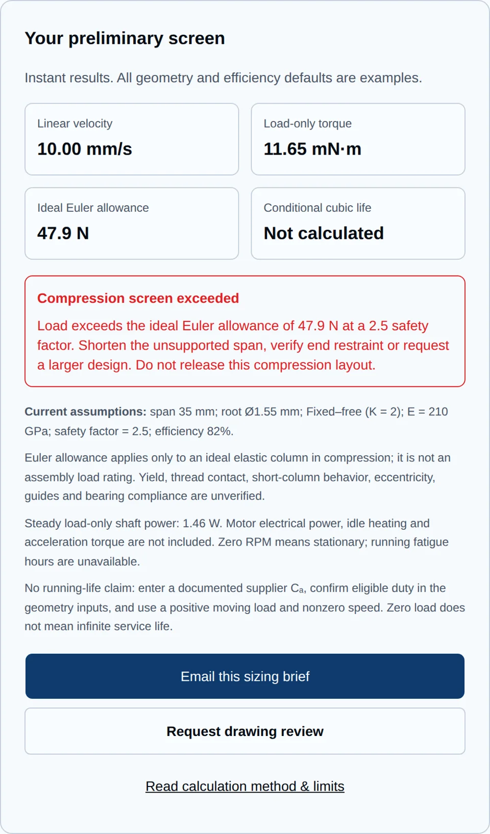
Instant results. All geometry and efficiency defaults are examples.
Linear velocity
10.00 mm/s
Load-only torque
11.65 mN·m
Ideal Euler allowance
47.9 N
Conditional cubic life
Not calculated
Current assumptions: span 35 mm; root Ø1.55 mm; Fixed–free (K = 2); E = 210 GPa; safety factor = 2.5; efficiency 82%.
Euler allowance applies only to an ideal elastic column in compression; it is not an assembly load rating. Yield, thread contact, short-column behavior, eccentricity, guides and bearing compliance are unverified.
Steady load-only shaft power: 1.46 W. Motor electrical power, idle heating and acceleration torque are not included. Zero RPM means stationary; running fatigue hours are unavailable.
No running-life claim: enter a documented supplier Cₐ, confirm eligible duty in the geometry inputs, and use a positive moving load and nonzero speed. Zero load does not mean infinite service life.
Four decisions before selecting a 2 mm assembly
Confirm the package dimension
A nominal 2 mm shaft does not define the nut, motor bore or bearing envelope. Establish the overall layout before assuming a fit.
See basis & limitsUse the full compressed span
At fixed diameter and end restraint, doubling span reduces the ideal Euler load to one quarter. Working stroke alone cannot determine that load.
See basis & limitsRequest configuration-specific ratings
No public evidence reviewed here verifies continuous thrust, zero backlash or temperature limits for this 2 mm concept. Keep these as open procurement requirements.
See basis & limitsCompare complete actuator layouts
Integration can overlap components. Any axial saving must be calculated against a layout with the same travel and clearances.
See basis & limitsInverted architecture: useful integration, separate fit checks
Inversion changes the screw/nut/roller arrangement and permits direct push-tube integration. The rotating-nut sketch is one layout option. Moog’s architecture description supports this principle; it does not establish a 2 mm commercial assembly.
Compare extended and retracted CAD envelopes
| Dimension | Conventional layout | Integrated layout |
|---|---|---|
| Motor and coupling | Record motor length, coupling and bearing housing. | Record rotor bore, bearing stack and nut interface. |
| Stroke and rear clearance | Include the moving nut and full travel. | Include shaft entry, full extension and rear clearance. |
| Guidance and servicing | Include guide carriage and lubrication access. | Include anti-rotation, guide path and disassembly access. |
| Length saving | Baseline CAD dimensions required. | Unknown until both layouts meet identical requirements. |
Known inputs, assumptions and missing product evidence
| Parameter | Status on this page | Evidence needed |
|---|---|---|
| Nominal diameter | 2.0 mm target, not a released assembly drawing. | Dimensioned shaft, nut and motor envelope. |
| Root diameter / leads | 1.55 mm root and 0.4 / 0.5 / 1.0 mm leads are illustrative inputs. | Minimum root section and manufactured lead confirmed on drawing. |
| Dynamic / static ratings | Unknown; no default Cₐ is inserted into life calculations. | Supplier Cₐ / C₀ₐ, rating method, configuration and preload. |
| Continuous force / speed | Unknown. Tool ranges are numerical bounds only. | Representative temperature-rise and endurance tests at the full duty profile. |
| Backlash / accuracy / drag | Unknown; no zero-play or sub-micron claim. | Measured reversal displacement, drag torque and lead error under agreed conditions. |
| Materials / lubrication / availability | Project-specific; no stock, certification or delivery promise. | Material certificates, lubricant compatibility, supplier process and quotation. |
Reproducible calculation method and its limits
| Output | Method | Limit |
|---|---|---|
| Feed speed (mm/s) | v = n × lead / 60; n in RPM, lead in mm. | Constant speed; no acceleration or controller model. |
| Load-only torque (mN·m) | T = F × lead / (2π × η), with η entered as a fraction. | Steady forward drive only. Add measured drag, inertia and other losses for motor sizing. |
| Load-only shaft power (W) | P = 2π × n × T / 60000, T in mN·m. | Not motor electrical input or a heat-rise prediction. |
| Ideal Euler allowance (N) | I = πdᵣ⁴/64; Pcr = π²EI/(KL)²; allowance = Pcr/2.5. E = 210000 N/mm². | Ideal elastic straight column, compression only. E and the safety factor are assumptions; yield and short-column limits are not assessed. |
| Conditional cubic fatigue | L = (Cₐ/F)³ × 10⁶ rev; moving h = L/(60n); elapsed h = moving h / moving-duty fraction. | Only with supplier-confirmed rating, cubic method and eligible duty; positive load and speed. No universal exponent claim from ISO bearing standards. |
| Full out-and-back cycles | Cycles = L × lead / (2 × stroke). | Constant load both directions and complete strokes. Short-stroke dithering, shock and internal preload are excluded. |
The velocity, torque and optional cubic-life relations follow the Ewellix calculation formulae. Schaeffler’s selection tool treats buckling length, stroke, restraint and compression separately. Here K = 2, 0.7 and 0.5 are ideal column models. Real support compliance and eccentric loading can reduce capacity; short columns require additional material/yield checks.
A smaller diameter reduces ideal buckling load with its fourth power. Do not apply a product’s rating to another lead, nut, preload or contact geometry. Variable-load motion requires the supplier’s equivalent-load method; average force and moving duty cannot replace it. This tool does not check contact stress, preload fatigue, critical speed, bearing life or backdrive holding.
Three reproducible concept screens
Illustrative calculations, not customer test cases. All use 0.5 mm lead, 1.55 mm root, 82% assumed efficiency, E = 210 GPa and a 2.5 Euler safety factor. Cₐ is absent, so service life remains unknown.
| Concept and inputs | Calculated result | Next action |
|---|---|---|
| Guided finger concept: 120 N, 1800 RPM, 18 mm stroke, 35 mm span, fixed-supported. | 15.00 mm/s; 11.65 mN·m; Euler allowance 391.3 N. Geometry screen only — capacity unverified. | Check lateral pinch moments, actual guide stiffness and motor heating; obtain a supplier rating. |
| Long unsupported push rod: 150 N, 800 RPM, 25 mm stroke, 50 mm span, fixed-free. | 6.67 mm/s; 14.56 mN·m; Euler allowance 23.5 N. Compression screen exceeded. | Revise unsupported length or load path before seeking a compression design approval. |
| Low-force optical concept: 25 N, 600 RPM, 8 mm stroke, 20 mm span, fixed-supported. | 5.00 mm/s; 2.43 mN·m; Euler allowance 1198.4 N. Geometry screen only — capacity unverified. | Measure reversal error, drag and thermal drift; no optical positioning accuracy is inferred. |
Manufacturing and inspection questions that affect cost
A 2 mm nominal shaft does not imply a 2 mm nut bore. Ask the supplier to review the actual internal thread geometry, access length, tooling, heat treatment distortion and inspection access. No proprietary process or tolerance capability is established by this page.
| Requirement | Request in the quotation | Cost or release risk |
|---|---|---|
| Thread geometry | Supplier drawing and proposed process for the actual bore and engagement. | Custom tooling, first-article development and scrap exposure. |
| Preload and reversal | Specify reversal load, displacement, drag and temperature during measurement. | Tighter matching can increase sorting, assembly and motor requirements. |
| Lead and runout | Agree measurement length, datum, instrument and acceptance band. | A catalogue accuracy class alone does not settle short-travel error. |
| Traceability and samples | Material / heat-treatment records, sample plan, NRE and delivery milestones. | Additional certification, inspection and qualification must be priced explicitly. |
Misuse, cost and application-fit risks
| Risk | Mitigation | Alternative to evaluate |
|---|---|---|
| Using Euler allowance as a force rating | Obtain assembly static/dynamic ratings and check the complete compressed load path. | Shorter unsupported span, lower force or a larger qualified assembly. |
| Lateral loads and misalignment | Size a separate guide path and inspect coaxial alignment throughout travel. | Guided actuator module with defined moment capacity. |
| Dither, dwell and lubricant starvation | Qualify representative stroke amplitudes, dwell times and replenishment motion with the lubricant supplier. | A different motion strategy or lubrication system; no universal purge interval. |
| Heat and holding duty | Measure enclosed motor/nut temperatures and drag at the target duty. Verify power-off behavior. | Separate motor packaging, cooling path or an independently rated holding brake. |
| Custom-part cost and schedule | Get written tooling/NRE, first-article, sample and metrology scope. | Compare documented ball-screw, sliding-screw or larger integrated options on total system cost. |
| Medical, vacuum or cryogenic fit | Require application-specific material, cleanliness, lubricant and endurance qualification. | An already qualified module where the evidence and envelope fit. |
Compare technologies using the same requirements
| Option | Reason to investigate | What to confirm |
|---|---|---|
| 2 mm inverted concept | Potential motor / nut overlap in a very small mechanism. | Feasibility, actual nut diameter, rating, drag, tooling and assembly access. |
| Miniature ball screw | An available catalogue part may simplify sourcing and inspection. | Actual product ratings, preload, nut envelope and system travel. |
| Miniature sliding screw | May suit lower duty or a simpler cost target. | Wear, efficiency, reversal clearance and tested holding behavior. |
| Larger inverted assembly | May provide more room for bearings, stiffness and manufacturing. | Documented assembly envelope and ratings; size alone does not prove suitability. |
Explore the adjacent 1.5 mm concept, standard 2 mm micro planetary roller screw or 10 mm architecture when the diameter requirement changes. Confirm their product data independently for your assembly.
Sources, date and evidence boundary
Sources reviewed November 10, 2026. These manufacturer references support architecture and calculation methods. They do not certify a Micro Roller Screw 2 mm product, factory test result, lubrication regime or commercial availability. No public 2 mm test report was established in this review.
- Moog — Inverted Roller Screws
Architecture and integration principles only. Its published product ranges do not establish a 2 mm rating.
- Schaeffler — Ball and roller screw selection assistant
Separate inputs for stroke, buckling length, end restraint and load direction; Euler applies to compression.
- Ewellix — Roller screws, IL-05003/1-EN, June 2020 (manufacturer PDF, distributor mirror)
Printed pages 44–46: cubic basic life, mean load, drive torque and power. No extrapolation of catalogue ratings to this 2 mm concept.
2mm inverted roller screw questions
Geometry and calculation
Does 2 mm describe the whole actuator?
No. Here it means the target nominal screw diameter. Nut outside diameter, bearings, motor bore and total extended length need a separate assembly drawing. Root diameter must also be confirmed.
Is unsupported span the working stroke?
No. Span is the compressed free length between actual restraints at the worst extension. Travel can exclude mounting offsets and overhangs. Enter span independently and verify the full load path.
Why is the default support fixed–free?
It avoids assuming a front guide provides ideal lateral restraint. Other end models are available, but the real support stiffness must justify the selected model. An ideal Euler calculation cannot check that stiffness.
Can I enter zero load or zero speed?
Yes. Zero speed gives zero feed and steady shaft power; running fatigue hours are unavailable. Zero load gives zero load-only torque, but does not remove friction, preload drag or heating. Life is not shown as infinite.
Evidence and performance
Is 200 N a verified continuous load rating?
No verified 2 mm assembly rating is established here. The input range is a numerical tool boundary. Ask for configuration-specific dynamic and static ratings, thermal tests and acceptance conditions before selecting a load.
Why is fatigue life blank by default?
A documented assembly dynamic rating is missing. Enter a supplier rating and confirm the eligible full-stroke, unpreloaded duty only when the supplier accepts the cubic method. The resulting constant-load illustration is not measured service life or a warranty.
Does preload guarantee zero backlash or sub-micron positioning?
No such guarantee is established for this concept. Request reversal-load displacement, preload force, running drag, temperature and measurement conditions. Positioning also depends on the complete drive, control and guide system.
Will the inverted design save 50% of actuator length?
The architecture can overlap components, but a percentage is not established here. Compare both CAD layouts at identical travel, force, motor, bearings and clearance requirements.
Integration and purchasing
Can this tool select a motor?
It estimates steady torque caused by axial load using an assumed forward efficiency. Motor selection additionally needs preload and seal drag, acceleration, rotor inertia, holding behavior and a thermal duty study.
Can the shaft carry side loads?
This tool assumes a centered axial load. Give side forces and moments to a separately sized guide system and check alignment and load transfer. It does not calculate radial or moment capacity.
Which grease, coating or flushing interval should I specify?
No universal product or interval is established. Give temperature, motion amplitude, dwell time, contamination and material constraints to the supplier, then qualify the proposed lubricant and maintenance motion on representative hardware.
What should I send for a quotation or CAD review?
Send nominal and root diameters, lead, maximum unsupported span, full stroke, motor envelope, bearing and guide layout, load and speed history, life target, environment, drawings, sample quantity and annual volume. Ask for availability, NRE, inspection and acceptance scope.
Turn the screen into a reviewable drawing brief
Send the calculator brief with your load history and dimensioned assembly. Request confirmation of geometry, ratings, drag, lubricant and inspection scope before freezing the design. If inputs are unknown, send a marked-up concept drawing for feasibility review first.
Inquiry Email
Please include screw type, diameter, lead, stroke, load, drawings, STEP files, and quantity timeline.
NDA signing supported prior to drawing uploads.
Instant Chat
WhatsApp Engineering SupportQuick clarification for drawings, sample photos, and lead-time checks. Complete RFQs are usually triaged within one business day.