
2mm Micro Roller Screw
Estimate velocity, load-only torque and ideal column buckling. Edit assumptions below; 2 mm denotes shaft diameter, and supplier feasibility remains unverified.
Request a drawing reviewScreening Calculation Summary
Geometry screen only — capacity unverifiedStatic default example. Enable JavaScript to edit inputs and calculate; use the method or drawing review links below.
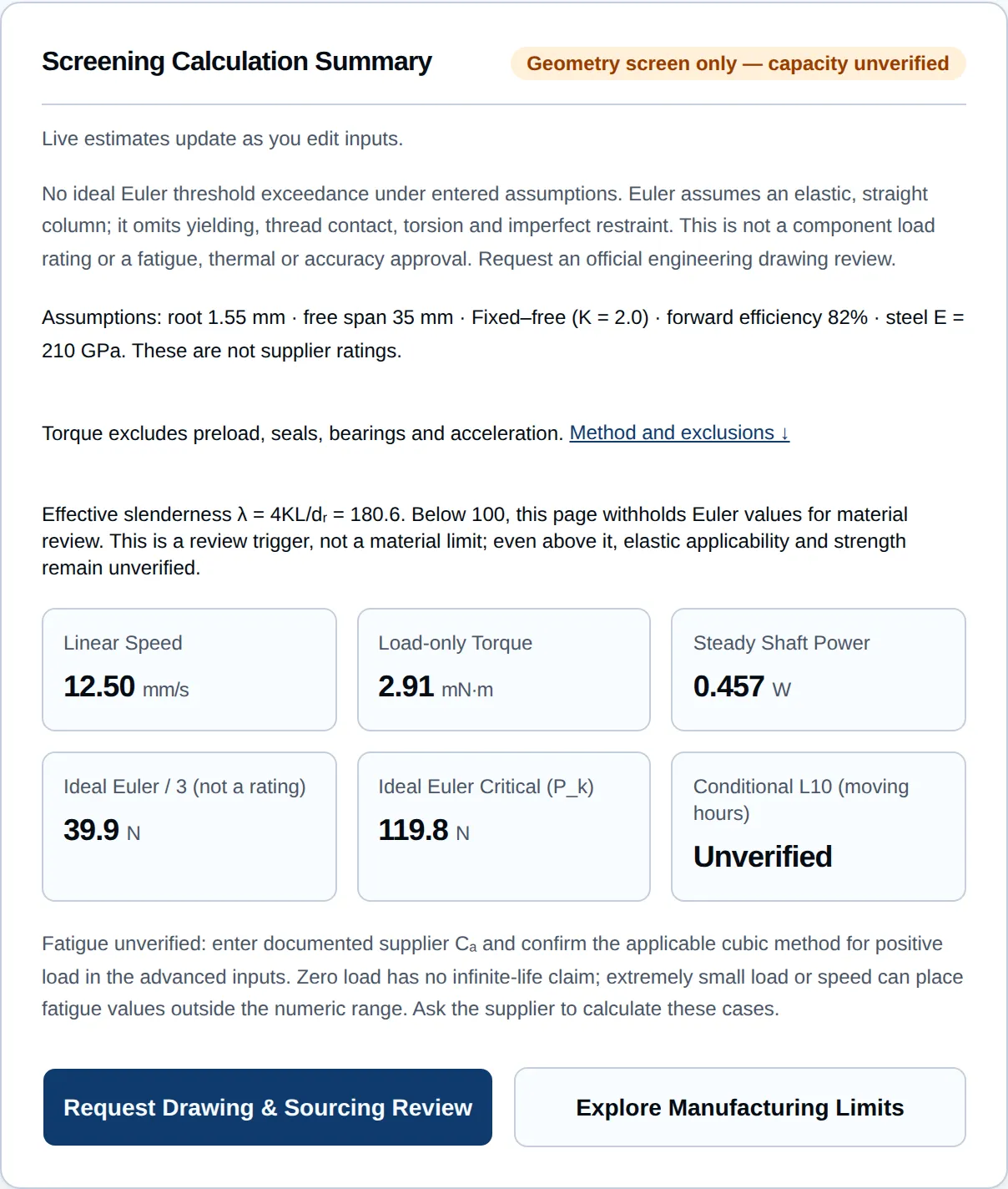
No ideal Euler threshold exceedance under entered assumptions. Euler assumes an elastic, straight column; it omits yielding, thread contact, torsion and imperfect restraint. This is not a component load rating or a fatigue, thermal or accuracy approval. Request an official engineering drawing review.
Assumptions: root 1.55 mm · free span 35 mm · Fixed–free (K = 2.0) · forward efficiency 82% · steel E = 210 GPa. These are not supplier ratings.
Torque excludes preload, seals, bearings and acceleration. Method and exclusions ↓
Effective slenderness λ = 4KL/dᵣ = 180.6. Below 100, this page withholds Euler values for material review. This is a review trigger, not a material limit; even above it, elastic applicability and strength remain unverified.
Linear Speed
12.50 mm/s
Load-only Torque
2.91 mN·m
Steady Shaft Power
0.457 W
Ideal Euler / 3 (not a rating)
39.9 N
Ideal Euler Critical (P_k)
119.8 N
Conditional L10 (moving hours)
Unverified
Fatigue unverified: enter documented supplier Cₐ and confirm the applicable cubic method for positive load in the advanced inputs. Zero load has no infinite-life claim; extremely small load or speed can place fatigue values outside the numeric range. Ask the supplier to calculate these cases.
Important Engineering Scope & Safety Notice:
- Root diameter 1.55 mm is an example assumption for a nominal 2.0 mm shaft, not a typical or verified product dimension.
- The ideal Euler threshold falls with span squared. It excludes yielding and contact capacity, especially important for short columns. Verify actual shaft bearings and material strength.
- Route payload side loads and moments through suitable guides. Guidance does not by itself establish shaft end restraint. Confirm alignment, interfaces and ratings with the supplier.
Four decisions before requesting a 2mm micro roller screw
Prepared by Micro Roller Screw. Source and assumption review: . This is a concept screening guide; no reviewed document establishes a rated, available nominal 2 mm assembly.
| Decision | Evidence or assumption | Next action |
|---|---|---|
| Define the whole package | 2 mm shaft diameter does not specify root, nut or support dimensions. | Obtain a dimensioned assembly drawing. |
| Screen compression separately | Euler thresholds scale as root diameter⁴ / span² under ideal restraint. | Verify free length, actual bearings and material strength. |
| Treat fine leads as hypotheses | 0.2–1.0 mm choices are kinematic examples; feasibility is unverified. | Ask which screw family and lead can be manufactured. |
| Qualify operating duty | Lubrication, preload and life depend on the assembly and duty. | Obtain ratings, method and a prototype test plan. |
View the reproduced calculator result
Manufacturer catalogues explain general screw families and operating considerations. All 2 mm-specific dimensions and performance remain drawing-dependent. Source & scope ↓
Architecture: what is being screened?
A planetary roller screw transfers axial force through threaded rollers between a shaft and nut. The diagram identifies the concept only; roller count, profiles, timing geometry and outer envelope need a supplier drawing.
This model assumes an axial compressive load and a rotating threaded shaft. It does not select a finished component or design the roller contacts.
Rollvis catalogue, printed pp. 2–4, describes the conventional, inverted, recirculating and differential families. Source & scope ↓
| Layout | Packaging question | Evidence needed |
|---|---|---|
| Conventional planetary | Can the shaft, shorter nut, bearings and motor fit throughout travel? | Assembly envelope and moving-member drawing. |
| Inverted | Can an extended internally threaded nut fit the motor and stroke? | Compare the inverted concept and its limits |
| Differential / recirculating | Does an unusually fine lead require a different mechanism? | Supplier kinematics, speed and manufacturing feasibility. |
Compare mechanisms using assembly evidence
| Criterion | Roller-screw question | Alternative question |
|---|---|---|
| Force and life | What are this assembly’s Cₐ, static rating and approved duty? | What are the candidate ball screw’s documented ratings? |
| Positioning | What reversal error and loaded stiffness were measured? | Does a ball screw or flexure meet the same measured error budget? |
| Travel and speed | Is the proposed lead feasible in this screw family? | Would a lead screw, piezo or voice coil meet travel and control needs? |
| Cost and sourcing | What tooling, metrology, minimum order and prototype work are required? | Can a documented standard assembly reduce qualification work? |
A comparison is actionable only after the candidates are specified at the same force, travel, error budget and duty. No cost, load advantage or delivery claim is established by nominal diameter.
Calculation method, units and exclusions
| Output | Equation | Limit |
|---|---|---|
| Velocity (mm/s) | v = n × p / 60 | Lead is hypothetical until confirmed. |
| Load-only torque (mN·m) | T = F × p / (2πη) | Excludes preload, seals, bearings, acceleration and holding behaviour. |
| Steady shaft power (W) | P = 2πnT / 60000 | Mechanical power, not motor electrical input or heat generation. |
| Ideal Euler load (N) | I = πdᵣ⁴/64; Pcrit = π²EI/(K×L)² | Straight, elastic column. Yield, thread contacts and torsion are omitted. |
| Screening threshold (N) | Pscreen = Pcrit / 3 | E = 210000 N/mm² and factor 3 are assumptions, not a product rating. |
| Conditional fatigue | L10 = (Cₐ/F)³ × 10⁶ revolutions | Supplier-approved cubic method only; constant positive load and applicable unpreloaded duty. |
| Moving and elapsed hours | h = L10/(60n); elapsed = h/(duty%/100) | Positive speed only. Calendar conversion does not include ageing or validate heat. |
| Out-and-back cycles | cycles = L10 × p / (2 × stroke) | One-way stroke; assumes the supplier approves the actual motion duty. |
The Ewellix screw manual supplies the cubic screw-life method and calculation context. L10 describes fatigue survival statistically; it does not cover wear, corrosion, shock or all failure modes. Source & scope ↓
ISO 3408-5 is a ball-screw standard. This page does not use it as certification for the roller-screw concept or transfer the bearing exponent 10/3. Source & scope ↓
Hypothetical lead matrix: travel and drive demand
| Lead (mm/turn) | Velocity (mm/s) | Torque (mN·m) | Shaft power (W) | Nominal spacing (nm/count) |
|---|---|---|---|---|
| 0.20 | 6.00 | 1.94 | 0.366 | 48.8 |
| 0.40 | 12.00 | 3.88 | 0.732 | 97.7 |
| 0.50 | 15.00 | 4.85 | 0.915 | 122.1 |
| 1.00 | 30.00 | 9.70 | 1.829 | 244.1 |
Changing lead changes travel per revolution and required load torque. Encoder spacing alone says nothing about loaded accuracy. The assumed efficiency is editable in the tool and is not measured 2 mm performance.
Column buckling: a model threshold, not a load rating
The unsupported span is the maximum compressed free length, not the travel. Under the same ideal model, doubling span quarters the Euler threshold; doubling root diameter multiplies it by sixteen.
Euler theory requires elastic behaviour. A short column with strong ideal restraint can produce a very high number even though yielding, contact failure or bearing compliance governs first. No cell below establishes safe application load.
Do not change K merely because a carriage has guides. Confirm the shaft bearing arrangement and load path. Compression also requires static contact and material-strength checks.
Values are withheld for effective slenderness λ = 4KL/dᵣ below 100. This page review trigger is not a material limit. Even for displayed values, confirm elastic applicability, strength and actual restraint. Factor 3 follows the cited Ewellix column-screen convention.
| Free span (mm) | Fixed–free K=2 | Fixed–pinned K=0.7 | Fixed–fixed K=0.5 |
|---|---|---|---|
| 15 | Withheld: material review | Withheld: material review | Withheld: material review |
| 25 | 78.3 | Withheld: material review | Withheld: material review |
| 35 | 39.9 | Withheld: material review | Withheld: material review |
| 50 | 19.6 | Withheld: material review | Withheld: material review |
| 70 | 10.0 | 81.5 | Withheld: material review |
Separate shaft support from payload guidance
Document how the guides carry payload side forces and moments, how the screw transmits thrust, and how the bearings constrain the shaft. Ask for a compliant interface only after checking alignment, required axial stiffness and reversal error. A flexure or spherical seat has design-specific limits; no universal angular margin or isolation percentage is assumed here.
Dithering, lubrication and temperature: qualify the duty
Rollvis printed pp. 18–20 ties lubricant choice and maintenance to operating conditions and handling. It supplies no universal 2 mm grease or flushing schedule. Source & scope ↓
| Risk | Missing evidence | Minimum next step |
|---|---|---|
| Short oscillations / fretting | Wear and lubrication at actual amplitude, frequency and dwell. | Agree representative endurance testing and permitted replenishment motion. |
| Thermal growth / preload | Actual shaft and housing temperatures, materials and stiffness. | Measure steady and transient temperatures plus hot drag and reversal error. |
| Autoclave / cleaning | Full-assembly compatibility for the exact process and cycle count. | Request qualification records; material or grease alone is insufficient. |
| Vacuum / cleanroom | Assembly outgassing, particles, wear debris and process compatibility. | Define environment-specific acceptance and test the complete mechanism. |
| Shock / holding | Static capacity, shock spectrum, backdrive and brake behaviour. | Review the failure response and test the actual mounting. |
For a thermal estimate, calculate each part’s free growth using ΔL = αLΔT. Differential growth also depends on geometry and constraints; converting it into preload requires an assembly stiffness model. The tool’s shaft power is not a heat-dissipation prediction.
Preload and accuracy need an error budget
Set limits for loaded reversal error, elastic displacement, running torque and temperature. Compare measured behaviour with clearance and with supplier-defined preload. Feedback may correct measured position errors, but it cannot remove elastic motion or heat at the mechanism. Include motor torque reserve for acceleration and drag.
Worked examples you can reproduce in the tool
Hypothetical concepts only. All use root = 1.55 mm and efficiency = 82%; no supplier rating or fatigue life is assumed. These are calculations, not field case studies or application approvals.
Compact gripper concept
F=80 N · n=1800 RPM · lead=0.5 mm · stroke=14 mm · span=25 mm · Fixed–pinned (K = 0.7).
- Velocity
- 15.00 mm/s
- Load-only torque
- 7.76 mN·m
- Ideal Euler / 3
- Withheld: material review
Column model needs material review
Confirm shaft bearing restraint and gripper side-load path; an ideal column screen cannot establish grip impact capacity.
Enter these assumptions in the tool ↑Long extension concept
F=120 N · n=900 RPM · lead=0.5 mm · stroke=20 mm · span=35 mm · Fixed–free (K = 2.0).
- Velocity
- 7.50 mm/s
- Load-only torque
- 11.65 mN·m
- Ideal Euler / 3
- 39.9 N
Compression screen exceeded
Ideal threshold is exceeded. Revisit span, diameter and support architecture before sourcing.
Enter these assumptions in the tool ↑Optical positioning concept
F=15 N · n=600 RPM · lead=0.4 mm · stroke=18 mm · span=30 mm · Fixed–free (K = 2.0).
- Velocity
- 4.00 mm/s
- Load-only torque
- 1.16 mN·m
- Ideal Euler / 3
- 54.4 N
Geometry screen only — capacity unverified
Confirm loaded positioning error and wear at the actual dither amplitude; command spacing is not accuracy.
Enter these assumptions in the tool ↑Stationary holding concept
F=40 N · n=0 RPM · lead=0.5 mm · stroke=15 mm · span=35 mm · Fixed–free (K = 2.0).
- Velocity
- 0.00 mm/s
- Load-only torque
- 3.88 mN·m
- Ideal Euler / 3
- 39.9 N
Compression screen exceeded
Zero shaft power does not establish holding safety. Check brake, static rating and motor holding losses.
Enter these assumptions in the tool ↑What is known, assumed and still unknown?
| Item | Status | Required evidence |
|---|---|---|
| Kinematics and ideal column equations | Calculated model | Check inputs, units and actual applicability. |
| Root 1.55 mm, E 210 GPa, η 82%, SF 3 | Explicit example assumptions | Drawing, material and approved design factors. |
| Lead availability, nut dimensions, roller count | Unknown | Supplier assembly drawing and manufacturability review. |
| Cₐ, static rating, speed limit, stiffness | Unknown | Configuration-specific supplier documentation and method. |
| Thermal duty, wear, lubrication, sterilization | Unknown | Operating specification and complete-assembly qualification. |
| Price, tooling, minimum order and lead time | Unknown | Written quote tied to drawing revision and acceptance plan. |
Drawing review, manufacturing evidence and cost risks
| Review item | Supply or request | Why it affects the decision |
|---|---|---|
| Drawing and support | Root, free span, travel, envelope, journals, bearing arrangement and datums. | A nominal shaft diameter is insufficient for fit or strength. |
| Motion and loads | Force/time profile, peaks, RPM, dwell, duty and target life. | Constant-load screening cannot represent all service conditions. |
| Functional acceptance | Measured reversal error, loaded displacement, torque, temperature and wear. | Avoid unsupported zero-backlash or accuracy promises. |
| Metrology | Agreed lead/profile/runout limits, test load, temperature and measurement uncertainty. | Inspection effort may dominate small-batch cost. |
| Commercial exposure | Tooling/NRE, prototype count, scrap assumptions, inspection scope and repeat-order basis. | Compare total qualification cost with a standard alternative. |
Send the tool brief with the drawing revision, permitted environment and acceptance targets. Ask the supplier to identify which parameters are confirmed, conditional or unavailable before committing to the mechanical layout.
Primary sources and scope of evidence
Links checked on . Catalogue publication dates are historical; the review date does not imply updated ratings or stock. Public standard abstracts establish scope only.
Rollvis — Satellite Roller Screws, 2018 catalogue ↗
Printed pp. 2–4: contact paths and screw families; pp. 11–15: fatigue, rigidity and drive calculations; pp. 18–20: lubrication and handling. General manufacturer principles, not evidence of a nominal 2 mm product or its performance.
Ewellix — Roller screws, IL-05003/1-EN, June 2020 (distributor-hosted manufacturer PDF) ↗
Calculation formulae, printed pp. 44–45: cubic basic rating life, torque and shaft buckling. The tool uses these as a conditional method; a supplier must approve applicability. This historical edition does not establish current 2 mm availability.
ISO 3408-5:2006 — Ball screws: load ratings and operational life ↗
The public abstract establishes ball-screw scope. It does not certify this roller-screw concept, provide its rating, or justify transferring a rolling-bearing exponent to it.
Frequently asked engineering questions
Geometry & immediate sizing
What does 2mm mean here?
This page uses 2 mm as the nominal shaft major diameter. It is not the lead, roller diameter or nut envelope. Root diameter 1.55 mm is an editable example; no supplier drawing establishes the actual value.
Are the calculator leads available products?
No availability is established here. The 0.2, 0.4, 0.5 and 1.0 mm choices explore kinematics. Ask a supplier to confirm a feasible screw family, lead and assembly envelope before specifying one.
Why are stroke and unsupported span separate?
Stroke is one-way travel. Span is the compressed free shaft length at the worst extension, including overhangs and offsets. The Euler result uses span; fatigue cycle conversion uses stroke.
Does a value below the Euler threshold prove the screw is safe?
No. The ideal elastic column calculation excludes yielding, contact capacity, torsion, shock, misalignment and actual bearing compliance. Short, stiffly restrained columns especially require a separate material-strength check.
Motion, fatigue & accuracy
Why is L10 life unverified by default?
A nominal diameter supplies no dynamic rating. Enter documented supplier Cₐ and confirm that the cubic method applies to the stated unpreloaded, constant-load duty. L10 is a statistical fatigue estimate, not a guaranteed service interval.
Why not automatically use the roller-bearing exponent 10/3?
Rolling-bearing formulae and roller-screw rating methods are not interchangeable. The cited Ewellix screw calculation uses a cubic relation. If a supplier specifies another method, leave this tool’s fatigue confirmation unchecked and request that calculation.
What happens at zero load or zero speed?
Zero load gives zero load-only torque, not zero real drag or infinite life. At zero speed, velocity and steady shaft power are zero; holding torque, heating and static capacity remain separate checks. No moving-hour fatigue estimate is shown.
Does a fine lead or encoder count prove sub-micron accuracy?
No. Lead divided by counts per turn is only nominal command spacing. Loaded accuracy depends on lead error, reversal error, compliance, temperature, encoder location and controller performance.
Assembly & operating risks
Do carriage guides establish fixed–pinned shaft restraint?
No. Payload guides redirect side loads, but the shaft support model depends on bearings and the complete load path. Default fixed–free is a screening assumption, not proof of the actual mounting.
Can a micro roller screw carry radial loads?
Route payload side loads and moments through a separately designed guide structure. Obtain supplier limits and alignment requirements; this page provides no radial load rating or universal failure threshold.
Which grease and flushing interval should be used for dithering?
Neither can be set from nominal diameter alone. Supply stroke, frequency, dwell, load, temperature and environment to the supplier, then qualify wear and drag. A proposed sweep must also be compatible with the application’s permitted motion.
Can the assembly be autoclaved or used in a cleanroom or vacuum?
Compatibility is unverified. Alloy or grease choice alone cannot establish it. Request complete-assembly evidence for the exact sterilization cycle, cleanliness or vacuum requirement, including seals, corrosion, wear and retained performance.
Selection & sourcing
Is a roller screw always better than a miniature ball screw?
No. Compare actual assembly ratings, measured stiffness and reversal error, speed, packaging, sourcing cost and qualification work. The mechanism alone does not prove a fixed capacity multiplier or lower total cost.
How does the inverted architecture differ?
A conventional arrangement uses a threaded shaft through a shorter nut; an inverted arrangement places the working internal thread in an extended nut. Motion and motor integration depend on the specific design. Compare full envelopes and support layouts.
Can the tool predict critical speed, temperature or backdriving?
It does not solve those checks. Forward efficiency is an assumption for torque only. Obtain speed limits, measured thermal behaviour and holding or brake requirements from the supplier and system design review.
What should accompany a drawing review request?
Send a dimensioned drawing, actual root and free span, bearing arrangement, stroke, peak and sustained forces, RPM, duty and dwell, temperature, target life, permitted reversal error, quantity and environment. Request documented ratings and prototype acceptance criteria.
Request a 2mm micro roller screw feasibility review
Send your drawing, load profile and packaging limits. Request configuration-specific ratings, unresolved assumptions and a prototype test plan.
Inquiry Email
Please include screw type, diameter, lead, stroke, load, drawings, STEP files, and quantity timeline.
NDA signing supported prior to drawing uploads.
Instant Chat
WhatsApp Engineering SupportQuick clarification for drawings, sample photos, and lead-time checks. Complete RFQs are usually triaged within one business day.