
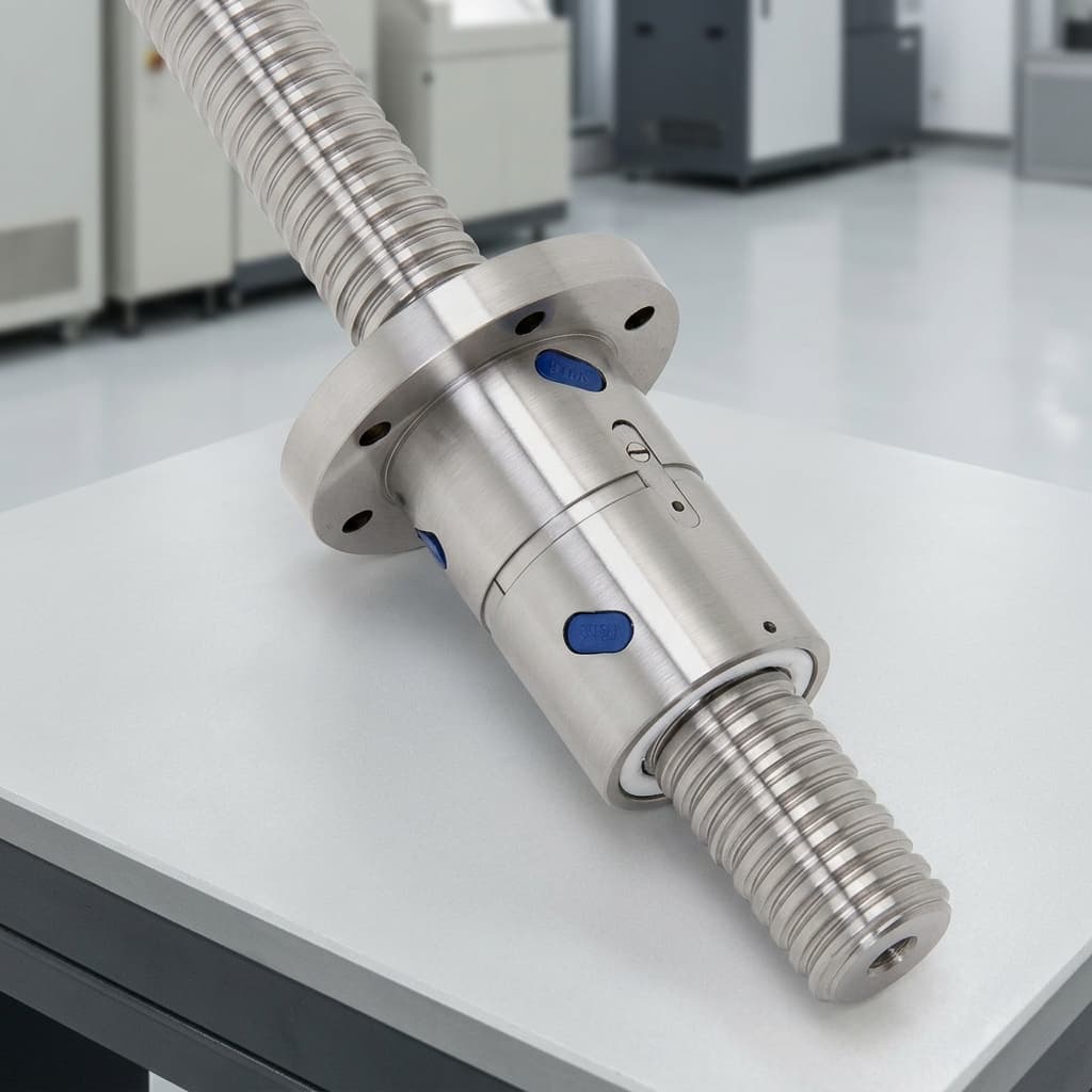
Preload Methods and Backlash Elimination in Micro Roller Screws: Sizing, Drag Torque, and Procurement Trade-Offs
Compare micro roller screw preload methods, estimate drag torque, and define backlash acceptance tests. Use the RFQ checklist to request an engineering review.
Micro roller screw preload reduces reversal clearance and increases contact stiffness, but it also adds friction, heat, and internal load. For engineers and procurement teams, the useful requirement is a measurable combination of axial play, loaded reversal displacement, and allowable drag torque—not an unqualified “zero backlash” note.
This guide compares split nuts, supplier-specific oversized-roller designs, and selective assembly for miniature electromechanical actuators. It includes a reproducible torque-budget example and an RFQ checklist for choosing between stiffness, motor size, packaging, and inspection cost.
Scope and evidence: Published and reviewed October 27, 2026 for global OEM sourcing of miniature planetary roller screws with nominal diameters of 1.5–8 mm. Calculations below are illustrative engineering screening, not measured product performance or application approval. Industrial catalogue methods require supplier confirmation before applying them to a micro assembly; medical, aerospace, and other regulated uses require separate qualification. Use our dynamic load rating sizing guide, review the lead accuracy class guide, or try the baseline L10 life calculator. A baseline life result does not include preload unless the selected rating and load model explicitly account for it. Request an engineering review with your reversal load, stroke, temperature range, and motor torque budget.
1. Backlash Elimination vs. True Preload: The Micro-Scale Dilemma
Before evaluating mechanical implementations, procurement and engineering teams must establish precise terminology. In mechanical catalogs and RFQs, "backlash" and "axial play" are often conflated, leading to expensive over-specification.
Contact Mechanics: Axial Clearance vs. True Preloaded Flank Contact
- Axial clearance (backlash, sa): Free relative axial travel before the opposite load-bearing flank engages. Specify the measurement force, temperature, mounting, and instrument resolution; clearance limits depend on the actual screw design.
- Selective assembly / low axial play: Matched components reduce free clearance without deliberately applying a substantial preload. An RFQ target such as
sa ≤ 3 µmis an acceptance requirement to be negotiated, not a universal miniature-screw capability. Residual clearance and elastic displacement still need measurement. - True preload (Fpr > 0): Opposing contacts carry an internal force before an external working load is applied. Loaded reversal behavior depends on contact stiffness, nut construction, supports, and preload. Do not apply one universal separation-load multiplier to every design.
Why Contact Geometry Matters
Planetary roller screws distribute load through multiple threaded roller contacts. Their contact geometry supports high load capacity in a compact envelope, but stiffness and friction depend on geometry, lubrication, alignment, and load. Neither a fixed stiffness advantage over ball screws nor a fixed micro-scale friction penalty can be assumed from contact type alone.
The Ewellix catalogue distinguishes axial-play, backlash-free, and preloaded constructions on printed pages 30–33. These are useful categories for an RFQ, not interchangeable performance guarantees.
2. The Three Primary Preload Architectures
When ordering micro roller screws, procurement teams typically encounter three core mechanical implementations. Each represents a fundamentally different compromise between axial stiffness, packaging length, dynamic capacity, and thermal stability.
Architecture A: Split Nut with Precision Spacer or Disc Springs (Axial Preload)
In a split-nut configuration, the nut body is divided transversely into two distinct halves.
- Rigid spacer preload: A calibrated spacer establishes the relative axial offset between nut sections and creates opposing contact forces.
- Spring-loaded preload: Where a supplier offers a spring arrangement, spring force and travel can accommodate some displacement. Its stiffness, relaxation, and available travel must suit the load cycle; a spring is not automatically a constant-force device.
[Nut section 1] <-- [Calibrated spacer or qualified spring] --> [Nut section 2]
Continuous screw shaft and roller contacts- Capacity trade-off: Nut sections share internal load differently as external thrust changes. Use the rating of the actual preloaded assembly rather than the rating of an otherwise similar single nut. The Exlar engineering catalogue, printed page 171, gives a 0.63 rating factor for its preloaded screws. This is a manufacturer-specific example, not a universal factor for micro roller screws, and must not be applied again to an already derated catalogue rating.
- Packaging trade-off: Obtain the actual assembly drawing, including adjustment, retention, and spring travel. A split nut does not imply a universal percentage increase in nut length.
- Reversal and shock trade-off: Request the load–displacement curve and the point at which an opposed contact unloads or spring travel is exhausted. Check both thrust directions.
Architecture B: Oversized Rollers (Supplier-Specific Single-Nut Preload)
Some suppliers offer a single-nut arrangement using selected roller dimensions to introduce interference. Ask the supplier to identify the actual contact and preload mechanism rather than assuming it is equivalent to a split nut.
- Potential advantage: A single nut may help meet a short actuator envelope. Its external dimensions and load rating still require confirmation for the chosen variant.
- Thermal sensitivity: Micrometre-scale changes in fit can change contact force and running torque. The effect depends on temperature gradients, materials, and mounting; a 25°C temperature rise does not establish that preload will double.
- Stroke and lead variation: Require full-stroke torque traces for the actual threaded length and lead class. There is no verified universal
L/d0 ≤ 20limit established by the sources cited here.
Architecture C: Precision Selective Assembly (Low-Play, Lightly or Non-Preloaded)
Selective assembly matches the shaft, nut, and rollers to a specified clearance and torque window. It is a candidate when the required loaded reversal accuracy can be met with less preload.
- Potential advantage: Lower intentional preload may leave more motor torque available for useful thrust and reduce frictional heating.
- Acceptance requirement: Measure residual play, breakaway torque, running torque, and loaded reversal displacement. Bearings, seals, lubricant, and rolling contacts still generate losses.
- Boundary: Selective fit does not guarantee zero drag, freedom from thermal binding, or a fixed micrometre deflection. An encoder and control loop cannot automatically remove mechanical deadband; encoder location and control dynamics matter.
3. Comprehensive Comparison: Preload Architectures
This six-option RFQ matrix compares design choices. Availability below 8 mm, capacity, dimensions, and temperature limits must be confirmed by the supplier; the entries are decision criteria rather than catalogue specifications.
| Architecture | Useful when | Main trade-off | Capacity basis | Required acceptance evidence |
|---|---|---|---|---|
| Standard clearance | The load is mainly unidirectional or reversal play is acceptable | Free travel during reversal | Selected assembly rating | Axial play under a stated test force; loaded reversal trace |
| Selective fit, low play | Motor torque is limited and the residual reversal error fits the budget | Low play is not a loaded stiffness guarantee | Rating of the matched assembly | Play, breakaway and running torque, loaded displacement |
| Oversized rollers, if offered | A single-nut envelope is essential | Fit and temperature gradients may change drag | Supplier-approved interference variant | Contact design, full-stroke torque, hot/cold tests |
| Split nut, rigid spacer | High reversal stiffness is needed in a defined thermal range | Preload changes internal loading | Actual preloaded assembly rating | Spacer setting, directional stiffness and torque trace |
| Split nut, spring arrangement | Some preload compliance is acceptable | Spring stiffness, fatigue, and travel affect behavior | Rating validated for the spring arrangement | Force–travel curve, reversal displacement, endurance evidence |
| Preloaded double nut | Packaging allows two nuts and their retention hardware | Extra length and mounting complexity | Rated complete pair, not an assumed sum | Assembly drawing, load sharing, alignment and torque report |
4. Drag Torque Calculation and the Motor Power Penalty
Keep external-load driving torque separate from preload friction. The Ewellix catalogue, printed pages 45–46, gives the following preload model for its designs:
Tpr = Fpr × Ph / (1000 × π) × (1/ηp − 1)       [N·m]
Tload = Fext × Ph / (2000 × π × ηp)            [N·m]
Trequired = Tload + Tpr + Tother + Jtotal × angular acceleration
Here Fpr is internal preload in newtons, Fext is external axial load in newtons, Ph is lead in millimetres, and ηp is practical direct efficiency. Tother covers bearing, seal, and other friction excluded from the screw model. Confirm the supplier's preload definition and efficiency model; do not use the external-load equation with Fpr substituted as an estimate of preload drag.
Worked Example: A 5 mm Screw and a 28 mN·m Motor
Illustrative inputs, not a tested product: diameter 5 mm; lead 1 mm; assumed preload 200 N; assumed efficiency 0.80; motor continuous torque 28 mN·m at the intended speed and cooling condition.
Tpr = 200 × 1 / (1000 × π) × (1/0.80 − 1)
    = 0.01592 N·m = 15.92 mN·m
Preload share = 15.92 / 28 = 56.8%

At an illustrative external load of 50 N:
Tload = 50 × 1 / (2000 × π × 0.80) = 9.95 mN·m
With an assumed 3.00 mN·m of other friction:
Trequired at constant speed = 15.92 + 9.95 + 3.00 = 28.87 mN·m
That constant-speed demand slightly exceeds the assumed continuous motor rating before acceleration. It identifies an inadequate continuous torque budget under these assumptions; it does not predict a particular stall time or winding temperature. Peak torque, RMS cycle torque, drive-current limits, and the actual torque–speed curve must also be checked.
The sensitivity table below holds lead, efficiency, and motor rating constant at the illustrative values above. Real efficiency and drag may change with preload, speed, lubricant, and temperature, so these are arithmetic comparisons rather than measured micro-screw ratings.
| Assumed preload Fpr (N) | Calculated Tpr (mN·m) | Share of 28 mN·m continuous torque | Remaining torque before load and other losses (mN·m) |
|---|---|---|---|
| 20 | 1.59 | 5.7% | 26.41 |
| 50 | 3.98 | 14.2% | 24.02 |
| 100 | 7.96 | 28.4% | 20.04 |
| 150 | 11.94 | 42.6% | 16.06 |
| 200 | 15.92 | 56.8% | 12.08 |
| 250 | 19.89 | 71.1% | 8.11 |
Procurement decision: Set the allowable drag window from the complete motor and thermal budget, then ask the supplier for the least preload that meets loaded reversal stiffness. A fixed 10–15% torque limit or 1–2% load-rating preload rule cannot replace application sizing. Send your torque budget and duty cycle for review before freezing the nut architecture.
5. The Thermal Runaway Trap in Miniature Actuators
A compact enclosed actuator may have limited heat rejection. If differential expansion tightens the contacts as friction increases, drag can rise further. The feedback loop below illustrates one possible failure mechanism; whether it occurs depends on the assembly and its operating conditions.
The Preload Thermal Runaway Feedback Loop
The Mechanism of Differential Expansion
For an illustrative 5 mm steel shaft, assume a thermal expansion coefficient of 11.5 × 10⁻⁶/K and a shaft temperature 40 K above its starting condition:
Change in shaft diameter = 5 mm × 11.5 × 10⁻⁶/K × 40 K
                         = 0.0023 mm = 2.3 µm
This is free shaft expansion, not an assembly interference or preload-force calculation. Nut and roller temperatures, material expansion, housing restraint, and contact geometry are needed to calculate the change in fit. Uniform heating of similar materials may produce a different result from a hot shaft inside a cooler nut. Do not infer a preload multiplier or seizure temperature from shaft expansion alone.
How to Address Thermal Binding at RFQ Stage
- Compare architectures at operating temperature: Ask for hot and cold torque and loaded reversal tests. If a spring arrangement is proposed, verify its stiffness, force range, and available travel.
- Agree on lubrication: Select lubricant viscosity and replenishment for the actual load, speed, and temperature; thinner lubricant is not automatically better. Our lubrication sourcing guide is related reading, not evidence of material compatibility for a particular actuator.
- Set a temperature-dependent clearance budget: Specify cold-start, steady-state, and temperature-gradient conditions. Ask the supplier to demonstrate acceptable play and torque throughout that range rather than targeting zero clearance at one assumed housing temperature.
6. Manufacturing Verification and Factory Quality Control
A small backlash target needs a measurement method whose uncertainty is appropriate to the tolerance. A product image does not establish measured backlash, roller grouping, manufacturing yield, or internal preload.
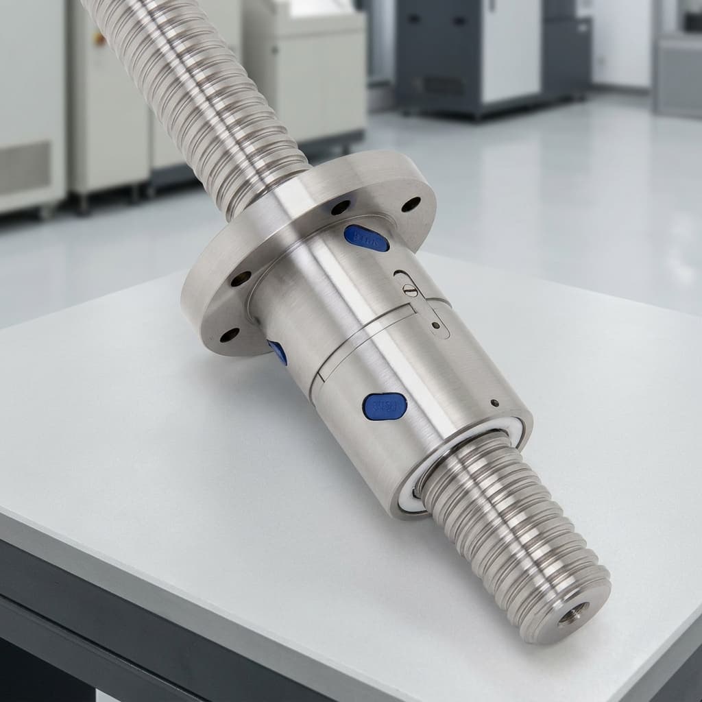 Illustrative assembly image. Request an identified sample drawing and inspection report to confirm dimensions, construction, and performance; the image is not metrology evidence.
Profile Measurement and Component Matching
Ask how the supplier measures thread profile, lead, and roller grouping, and how those measurements are traceable. Optical measurement may suit small features; contact metrology may also be appropriate where access and uncertainty permit. Request instrument resolution, calibration status, and a sample inspection report rather than prescribing a universal roller diameter, flank angle, or sub-micron sorting tolerance.
Continuous Running-Torque Logging
Specify lubricant, temperature, speed, run-in state, mounting, measurement uncertainty, and whether bearing and wiper drag are included. The Ewellix catalogue's printed page 32 uses 50 r/min and ISO VG 68 oil for its BR/PR types, with different oil for other types. Those conditions are a catalogue example, not a universal miniature-screw acceptance protocol.
ISO 3408-3:2006 covers ball screw acceptance conditions. If its methods are adapted by agreement for a roller screw, identify the agreed clauses and deviations; do not claim that it directly certifies every roller-screw design.
Request both travel directions over the usable stroke, including:
- Mean running torque: Verify the agreed acceptance window and report test speed and temperature.
- Torque variation: Report the maximum, minimum, and position-dependent trace; investigate unexpected peaks with the supplier.
- Breakaway torque: Measure separately after a specified dwell time, including cold-start conditions.
- Loaded reversal displacement: Measure at stated positive and negative forces so that free play and elastic compliance are not confused.
7. Engineering & Procurement Sourcing Checklist
To eliminate ambiguity and prevent costly redesign cycles, procurement and engineering teams should enforce the following checklist when submitting RFQs or approving first-article samples for zero-backlash micro roller screws in 2026.
Sourcing & RFQ Specification Checklist
- Quantified play target: State the axial-play limit, test force, mounting, and temperature; identify whether a value such as
sa ≤ 3 µmis actually required. - Loaded reversal requirement: Define reversing force, allowed displacement, and stiffness, separately from unloaded clearance.
- Drag and breakaway windows: Set separate maximum values from the motor budget; state speed, lubricant, dwell, and temperature conditions.
- Complete motor margin: Include useful thrust, acceleration, bearings, seals, torque–speed limits, cycle RMS torque, and heat rejection.
- Actual nut envelope: Approve the supplier drawing including spacer or spring travel, mounting, and usable stroke.
- Correct load-rating basis: Use the quoted preloaded assembly rating and supplier life method; avoid applying a derating factor twice.
- Temperature and duty cycle: Define cold start, hot operation, gradients, dwell, cycle frequency, and allowable temperature rise.
- Length and stroke validation: Confirm buckling, critical speed, lead variation, and full-stroke torque for the actual shaft length.
- Lubricant at acceptance and in service: Record both; agree how any oil-to-grease change will be qualified.
- First-article evidence: Require identified torque traces, loaded reversal measurements, measurement uncertainty, and the supplier's repeatability or yield evidence for the specified acceptance window.
If your team is finalizing an actuator envelope or struggling to balance backlash targets against motor size, contact our engineering team to review your CAD package and dynamic loading assumptions before releasing production tooling.
8. Frequently Asked Questions (FAQ)
What is the practical difference between a split nut and oversized rollers in micro roller screws?
A split nut establishes preload through an axial offset between nut sections. An oversized-roller design, where offered, changes component fit within a single nut. Compare actual nut length, preloaded load rating, loaded stiffness, and hot/cold drag; fixed capacity and length percentages are not universal.
Why can a split nut have a lower dynamic load rating?
Opposed nut sections carry different internal loads as external thrust changes, so a preloaded configuration may have a different rating from a single nut. Use the manufacturer's rating for that exact assembly. Exlar's 0.63 example applies to its described products; it is not a mandatory micro-screw derating rule.
When is selective assembly preferable to true mechanical preload?
Consider it when measured residual play and loaded reversal displacement meet the positioning requirement and the motor or heat budget is tight. It still requires operating-temperature tests and does not guarantee zero friction or eliminate mechanical deadband through control software.
How does preload affect the L10 fatigue life of a micro roller screw?
Preload changes internal contact loading during motion. Use the supplier's load-sharing and life method, including the rating of the preloaded assembly. Some catalogues, including the cited Exlar example, use a cubic load–life relationship; do not choose an exponent solely because the device contains rollers. Static dwell alone does not consume rolling-fatigue revolutions, but static overload, fretting, and short oscillations need separate checks. L10 is a statistical fatigue estimate, not a service-life guarantee.
Can we field-adjust the preload on a micro roller screw?
Only if the supplier provides an approved adjustment and requalification procedure for that design. Otherwise order a factory-set assembly and avoid disassembly that could disturb roller matching, alignment, lubrication, or cleanliness.
What is breakaway torque, and how does it relate to preload?
Breakaway torque is the torque needed to start motion after a dwell. Preload, lubricant, seals, temperature, and dwell time affect it. Request a separate cold-start and restart measurement; there is no established universal breakaway-to-running-torque ratio for all micro roller screws.
Conclusion: Balancing Rigidity, Heat, and Procurement Risk
Specifying zero backlash in a micro roller screw is not simply a matter of checking a box on a procurement requisition. In miniature electromechanical actuators, mechanical preload establishes an unforgiving trade-off between positioning stiffness, motor torque consumption, operating temperature, and component fatigue life.
By replacing vague "zero backlash" notes with explicit axial play limits, evaluating selective assembly for torque-constrained designs, applying appropriate load derating factors for split nuts, and auditing factory drag torque verification traces, procurement teams can protect their programs from prototype failure, motor overheating, and catastrophic supply chain delays.
Need to validate preload torque, nut envelope, or L10 life for your miniature actuator program? Contact our application engineering team to review your drawings, run sizing simulations, or request prototype samples.
Sources and References
Source scope checked October 27, 2026. These documents support terminology and manufacturer-specific methods; they do not establish miniature-product test results or supplier capability.
- ISO: ISO 3408-3:2006 — Ball screws — Part 3: Acceptance conditions and acceptance tests. Official standard record. Its stated scope is ball screws; any application of its methods to roller screws must be expressly agreed.
- Ewellix: Roller screws, IL-05003/1-EN, June 2020 — manufacturer catalogue, distributor-hosted PDF. Printed pages 30–33 describe play, preload, and torque testing; pages 45–46 provide the torque model used here. Confirm applicability to the selected micro design.
- Curtiss-Wright / Exlar: 2023 Engineered Product Catalog, revision 7-23, printed page 171. Manufacturer-specific travel-life method and preloaded rating factor. The document is search-indexed; its host may restrict automated PDF downloads. Obtain the current revision and assembly rating from the supplier.
Author

More Posts
How to Select the Right Inverted Roller Screw for Compact Aerospace Mechanisms
An engineering deep-dive into Inverted Roller Screws (RVi) for flight-control actuators, satellite deployment, and low-backlash aerospace mechanisms.
Planetary Roller Screw Accuracy Classes (C3 vs. C5 vs. C7): A Sourcing and Specification Guide
Compare C3, C5, and C7 planetary roller screw accuracy classes, lead error, lead-time risk, cost trade-offs, and RFQ rules for sourcing teams.
Planetary Roller Screw vs. Ball Screw: Which to Choose for High-Load Actuators?
An engineering and buyer's guide comparing planetary roller screws and ball screws. Includes load capacity data, Hertzian contact mechanics, and TCO analysis.