
12mm Planetary Roller Screw
Screen load, torque and speed now. Use the sourced guide below to compare planetary nut options and prepare a drawing review.
Screen your 12mm duty point
Live results below: speed, torque, single-nut fatigue life and structural limits. All duty inputs are required; defaults are an example.
Clicking "Email Sizing Brief" launches your default mail client with structured application parameters. Attach CAD or envelope drawings directly in your email.
What the screen can tell you
Prepared by Micro Roller Screw. Created (repository record). Evidence reviewed . Catalog editions are identified below; current availability and application approval remain to be confirmed.
Match the nut architecture first
The four RV benchmark leads below have separate single- and split-nut ratings. A split nut requires preload data before fatigue life can be evaluated.
Evidence and limits →Treat RPM as a screening limit
The catalog dn ceiling is reduced by shaft whirling, bearing limits and loaded dynamics. A nominal 12mm diameter alone does not establish operating speed.
Evidence and limits →Do not infer positioning accuracy from preload
Nut preload, shaft stretch, bearing compliance and housing stiffness all affect lost motion. The calculator reports shaft-only stiffness; full assembly stiffness is unknown.
Evidence and limits →Review the actual motion cycle
Constant-load fatigue life does not predict short-stroke wear, shock damage or lubricant life. Provide the complete force/speed spectrum and environment for selection.
Evidence and limits →Planetary mechanism and actuator packaging
A standard planetary assembly uses a central threaded shaft, orbiting threaded rollers and a surrounding nut. This page focuses on the traveling-nut planetary layout. The broader 12mm miniature guide covers general packaging selection; an inverted architecture needs its own nut and rotor envelope review.
Rollvis handbook, printed pp. 2–4 provides the architecture context. These schematics do not establish nut dimensions, shock endurance or a buildable actuator diameter.
Four sourced RV 12mm reference configurations
These are third-party benchmarks, not a MicroRollerScrew stock specification. Ca is a dynamic fatigue rating; C0a is a static rating, not a recommended continuous working load. Confirm the selected nut arrangement before applying either value.
| Lead (mm/rev) | Single Ca / C0a (kN) | Split Ca / C0a (kN) | Direct η | Root d2 (mm) |
|---|---|---|---|---|
| 1 | 13.6 / 25 | 7.5 / 12.5 | 78% | 11.89 |
| 2 | 14.6 / 26.9 | 8 / 13.4 | 86% | 11.81 |
| 4 | 17.2 / 27.2 | 9.5 / 13.6 | 89% | 11.6 |
| 5 | 18.1 / 27.3 | 9.9 / 13.6 | 89% | 11.49 |
Open the original ratings (printed p. 24) and root dimensions (printed p. 25). The 12×5 single-nut row lists maximum axial backlash of 0.05 mm; a universal 0.01–0.03 mm claim would be incorrect. Actual supplied play must be specified.
Reproduce the calculation and understand its limits
| Output | Formula | Assumption / missing data |
|---|---|---|
| Velocity | v = n × P / 60 (mm/s) | Constant commanded rotational speed. |
| Load-only torque | T = F × P / (2000πη) (N·m) | Catalog direct efficiency; no preload drag, seals, acceleration or motor inertia. |
| Shaft input power | W = T × 2πn / 60 | Mechanical input power, not motor electrical input. |
| Single-nut nominal life | L10 = (Ca / F)³ (million rev) | Nonzero constant load; valid lubrication and alignment assumed. |
| Life in hours | h = L10 × 10⁶ / (60n) | Nonzero speed; elapsed estimate = h / (duty / 100). |
| Static factor | s0 = C0a / Fpeak | Tool flags s0 < 2; this is a local screening target, not a universal standard. |
| Buckling allowance | Pk / 2.5; Pk = fkπ²EI / L²; I = πd2⁴/64 | Solid root section, E = 206,000 MPa; all peak thrust treated as compression. Factor 2.5 is a tool assumption. |
| Speed ceiling | min(0.8 × 108×10⁶ × 12 × fkr / L², 160000 / 12) | Zero axial load whirling estimate; does not certify loaded dynamics. |
Rollvis handbook, printed pp. 11–15 explains nominal life, compliance, speed and drive torque. The Euler/root-section calculation and 2.5 buckling factor here are explicit preliminary model choices, not the catalog’s own permissible-buckling formula.
Default inputs produce 120 mm/s, 2.504 N·m, 471.9 W and 1,099 running hours. The duty-adjusted estimate is 1,831 elapsed hours at 60% moving duty. It does not model idle-time damage or calendar service life.
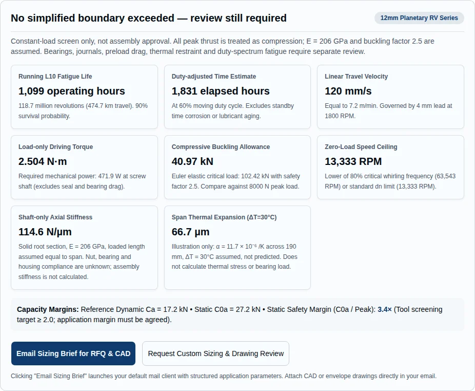
Request a drawing review using these inputs. If a peak is repeated during motion, its effect must enter a revolution-weighted equivalent load spectrum. Entering only a lower “running” force can overestimate fatigue life. Split-nut life is withheld until both nut halves’ internal loads are known.
Span, compression and speed are coupled
| Support | Euler fk | Whirling fkr |
|---|---|---|
| Fixed–supported (classic servo assembly) | 2.046 | 1.77 |
| Fixed–fixed (maximum buckling & critical speed) | 4 | 2.57 |
| Supported–supported (pinned ends) | 1 | 1.13 |
| Fixed–free (cantilevered actuator) | 0.25 | 0.4 |
The structural model uses ideal Euler end conditions; whirling factors follow handbook printed p. 13. Real bearings, reduced journals and load paths can lower these estimates. The nut is not counted as a radial shaft support. At high compression, obtain a coupled dynamic calculation even if the zero-load RPM check is clear.
Stroke is nut travel; span is the free shaft length used by the structural screen. Span must exceed stroke, but that alone does not prove packaging clearance: allow for nut length, bearings, journals and overtravel. Fixed–free arrangements need the actual free length from the fixed support.
Separate shaft stiffness from axis accuracy
| Loaded length (mm) | Shaft EA/L (N/µm) | Assembly stiffness / backlash |
|---|---|---|
| 100 | 217.7 | Unknown: requires nut, bearing and housing data |
| 200 | 108.9 | Unknown: requires nut, bearing and housing data |
| 300 | 72.6 | Unknown: requires nut, bearing and housing data |
The series-compliance relation is 1/Kaxis = 1/Kshaft + 1/Knut + 1/Kbearings + 1/Khousing. It requires actual component stiffness at operating load and preload. This tool assumes loaded shaft length equals span and reports only EA/L; the actual length varies with nut position and support arrangement. It makes no assembly stiffness or positioning guarantee.
Handbook printed p. 12 distinguishes component compliance. Catalog rigidity factors are not constant N/µm values and cannot be substituted as a fixed nut spring.
Thermal illustration: assuming α = 11.7×10⁻⁶ /K, a 200 mm freely expanding shaft grows 70.2 µm for an assumed 30°C rise. The calculator does not predict temperature or restrained thermal force. If both ends are constrained, review housing expansion, bearing loads and assembly tension together; do not apply an automatic pretension recipe.
Compare mechanisms using matched specifications
| Decision dimension | Standard planetary | Ball screw | Inverted roller screw |
|---|---|---|---|
| Contact / motion | Multiple threaded roller contacts; synchronized RV layout | Ball/raceway contacts; return path depends on design | Threaded roller contacts; rotating nut integration depends on design |
| Load and life | Use the exact selected nut rating | Obtain the exact diameter, lead and preload rating | Obtain the exact nut and shaft rating |
| Packaging | Review moving nut, flange and screw ends | Review nut and ball-return envelope | Review rotor, long nut and translating shaft |
| Cost and qualification | Quote grinding, preload, inspection and integration | Compare a qualified catalog alternative | Include custom rotor, bearing and validation cost |
For a cost-sensitive axis, compare a ball screw at the same duty and accepted backlash. For a rotor-integrated actuator, review an inverted layout. A shared nominal diameter is insufficient to claim a fixed load, acceleration or fatigue-life advantage.
Three reproducible hypothetical duty points
These are calculated examples, not customer deployments or endurance tests. They use the same model as the live tool. Values do not qualify medical, robotic or aerospace hardware.
A. Traveling-nut actuator
12×4, single nut; running / peak 2800 / 7500 N; 2400 RPM; stroke / span 65 / 140 mm; Fixed–supported (classic servo assembly); duty 45%.
- Speed
- 160 mm/s
- Load-only torque
- 2.003 N·m
- Running life
- 1,610 h
- Static factor
- 3.63
- Buckling allowance
- 75.5 kN
- Speed ceiling
- 13,333 RPM
Next step: Compare the fatigue estimate with the required life, then validate shock load, bearings and the actuator envelope. This does not establish robot durability.
B. Reversing precision axis
12×2, split nut; running / peak 3200 / 6800 N; 1500 RPM; stroke / span 90 / 180 mm; Fixed–fixed (maximum buckling & critical speed); duty 30%.
- Speed
- 50 mm/s
- Load-only torque
- 1.184 N·m
- Running life
- Not calculated — preload data needed
- Static factor
- 1.97
- Buckling allowance
- 95.9 kN
- Speed ceiling
- 13,333 RPM
Next step: This duty does not meet the tool’s static-factor target of 2.0. Revise peak load or nut selection; provide preload and thermal data before calculating life.
C. Fine-lead dispenser axis
12×1, split nut; running / peak 4200 / 4500 N; 300 RPM; stroke / span 40 / 95 mm; Fixed–supported (classic servo assembly); duty 80%.
- Speed
- 5 mm/s
- Load-only torque
- 0.857 N·m
- Running life
- Not calculated — preload data needed
- Static factor
- 2.78
- Buckling allowance
- 180.9 kN
- Speed ceiling
- 13,333 RPM
Next step: Fatigue life and assembly stiffness remain unknown. Validate preload drag, fluid-force transients and measured axis compliance before promising dispensing accuracy.
Wear, cost and application mismatch risks
| Risk | Missing evidence / consequence | Minimum next step |
|---|---|---|
| Misuse: oscillation and short stroke | Fatigue life does not quantify fretting or lubricant starvation. | Validate representative motion endurance; agree lubricant and redistribution motion with the supplier. |
| Misuse: lateral load and power loss | Side force, moments or unreviewed holding loads can invalidate axial sizing. | Use a verified guide/load path and validate the holding arrangement. |
| Cost: preload and custom materials | No verified price, lead-time, coating or specialty-alloy uplift is available. | Quote prototype and volume separately with inspection and qualification costs. |
| Mismatch: vacuum, cleanroom or corrosion | No assembly outgassing, cleanliness or environmental qualification is established here. | Specify exposure and acceptance tests; obtain compatible material and lubricant evidence. |
| Mismatch: thermal and high-speed duty | Temperature rise, preload drag and loaded vibration are not simulated. | Review thermal growth, bearing limits and a representative duty test. |
The ≤2.5 mm short-stroke advisory and compression above 20% of Euler load are conservative review triggers in this tool. They are not sourced universal failure thresholds. Do not infer a safe stroke, flushing distance, cycle interval or wear-life multiplier from them.
Specify acceptance evidence before ordering
ISO 3408-3:2006 covers ball-screw acceptance conditions and tests. It does not automatically certify this roller-screw assembly. Agree any adopted test method and tolerance with the supplier; no ISO, DIN, flight or medical qualification is asserted on this page.
- Define useful travel, lead deviation, repeatability, axial play and load-dependent stiffness separately.
- Request a traceable inspection report, shaft-end and bearing interfaces, preload/drag record and material documentation.
- Specify the environment and duty test, required sample quantity and pass criteria before production release.
Selection and integration FAQ
Architecture and selection
What does 12mm mean?
It is the nominal screw diameter, not the nut or actuator outside diameter. Check the complete nut, flange, bearings and motor dimensions on an approved drawing.
How does a planetary roller screw work?
Threaded rollers transmit axial force between the central screw and surrounding nut. In the standard RV architecture, end gearing synchronizes the rollers. The mechanism diagram is conceptual, not a manufacturing drawing.
Which lead should I choose?
At a fixed RPM, a larger lead gives more linear speed; at a fixed axial load it also requires more load torque. Compare the four sourced reference rows, motor speed and required travel before choosing.
Are these MicroRollerScrew stock ratings?
No. The named RV rows are third-party Rollvis catalog benchmarks. Availability, materials, ratings and dimensions for a supplied assembly require a quotation and drawing review.
Calculation and boundaries
What does L10 represent?
It is a nominal rolling-fatigue estimate at 90% survival for the specified constant-load single-nut model. It excludes wear, contamination, corrosion, shock damage and application qualification; it is not a warranty.
Why is split-nut life not calculated?
Internal preload changes the loads on both nut halves. Their individual fatigue lives and combined life require the actual preload and duty spectrum; substituting a lower catalog rating into the single-nut formula is insufficient.
What happens at zero load or zero RPM?
Zero running load suppresses fatigue life and gives zero load-only torque. Zero RPM gives zero speed and power and suppresses running-hour life. Neither state removes bearing drag, preload friction or holding-load requirements.
Is the displayed speed ceiling an approved operating speed?
No. It is the lower of the handbook dn limit and 80% of zero-load whirling speed for the selected support. Bearing limits, compression, journal geometry and real mounting stiffness still require review.
Integration and procurement
Does a preloaded nut guarantee sub-micron positioning?
No. Whole-axis positioning also depends on lead error, shaft and housing elasticity, bearings, feedback, temperature and controls. Request measured backlash, compliance and positioning acceptance criteria.
Is 2.5mm a universal short-stroke failure threshold?
No. It is a conservative review trigger used by this tool. Lubrication and wear depend on geometry and motion history; sweep distance and relubrication interval must be validated for the actual assembly.
Can a vertical axis rely on self-locking?
Do not assume the screw holds an external load when power is lost. Review backdriving and specify an independently validated holding arrangement for the machine and its operating conditions.
What should I send for CAD and RFQ review?
Send force and speed spectra, stroke and bearing span, mounting constraints, required life, backlash and stiffness targets, environment, quantity and timing. Use the calculator email brief, attach drawings in your mail client, or use the contact page.
Sources and evidence boundaries
Verified 2026-10-31. Original document editions below are distinguished from the verification date. Formulas and examples are preliminary calculations; no measured performance dataset is claimed.
- Rollvis RV product tables (2024 upload), printed pp. 24–25: selected single/split ratings, direct efficiencies and root diameters. The linked rows define the third-party benchmarks only.
- Rollvis satellite roller screw handbook (2018 edition): printed pp. 2–4 architecture; pp. 11–15 nominal life, compliance, zero-load speed and torque. Local screening factors and assumed steel properties are identified in the method section.
- ISO 3408-3:2006 official scope: ball-screw acceptance conditions and tests; linked to clarify scope, not to claim roller-screw certification.
Public evidence is insufficient here to establish assembly stiffness, acceleration limits, short-stroke endurance, coating benefits, specialty material availability, comparative price or shipment timing. These remain drawing- and application-specific review items.
Turn the screen into a drawing-review brief
Use the live tool’s email action to include the selected configuration and entered duty. Email opens your mail client; attach drawings there. If email is unavailable, use the contact page with the same inputs.