
Radial and Moment Load Survival in Micro Roller Screws: External Guide Sizing, Angular Misalignment Limits, and Preventing Roller Skewing in Precision EMAs
Size external guides for micro roller screws, budget angular misalignment, and prevent roller skewing. Use the worked example and RFQ checklist for EMA selection.
Design micro roller screws to transmit axial thrust, with external guides carrying radial forces and overturning moments. An axial load rating does not establish a permissible side load. Before selecting a miniature electromechanical actuator (EMA), calculate guide reactions at maximum extension and obtain the screw supplier's mounting and alignment requirements.
In compact robotic, medical, and optical mechanisms, removing the guides saves space but sends lateral reactions into the nut and screw supports. Misalignment changes thread contact positions and load distribution; roller skewing and interference can then increase friction and damage the mechanism. The Rollvis assembly guidance, printed page 20, specifically requires preventing radial forces and tilting moments on the nut.
This guide helps mechanical designers and procurement teams choose a guidance architecture, calculate external guide loads, and define evidence to request before releasing a purchase order.
Published and reviewed November 2, 2026. Scope: Global OEM engineering and procurement; English, SI units. The discussion concerns guided miniature planetary roller screw EMAs, with nominal shaft diameters approximately 1.5–10 mm. Manufacturer catalogs and research support the design principles, but do not qualify every micro size. Numerical examples below are hypothetical, reproducible statics and geometry calculations, not hardware test results. There is no universal allowable misalignment angle, radial-load percentage, or predicted failure life established here. Obtain limits for the selected screw, preload, supports, duty cycle, and temperature; regulated applications require their own qualification.
For related workflows, see dynamic load ratings and L10 life, accuracy classes and lead error, preload and backlash, and custom shaft end machining. For an architecture review, send your load case and guide layout.
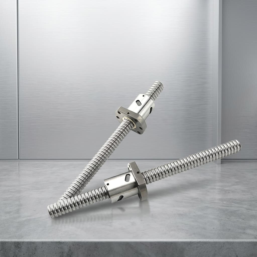
Header image: illustrative screw-and-nut assemblies. It does not show external guide rods, verified internal geometry, or a qualified actuator installation.
1. Kinematics of Radial and Moment Loading in Micro Roller Screws
In an aligned installation, threaded rollers transfer axial thrust between the screw shaft and nut. Multiple contacts provide axial stiffness and load capacity, but do not make the nut an external linear bearing. Even under axial load, real thread loads need not be equal: geometry, elastic deformation, and manufacturing error influence load sharing.
When a side force reaches a rigidly attached nut or push-tube, it can bend the shaft and tilt the nut relative to the screw. Contact positions and clearances change, with some regions carrying more load than others. The exact contact stresses require the selected geometry, material properties, preload, and boundary conditions; a side-force value alone cannot predict them.
Two published models provide useful context: Cai and colleagues' kinematics study links misalignment to transmission-velocity fluctuations, while their meshing study examines changes to contact positions and axial clearances. Neither abstract establishes a universal micro-screw seizure threshold.
The engineering response is to draw the complete load path: output load → guide bearings → housing. The nut connection must transmit the required thrust without forcing the screw to follow an incompatible guide axis.
2. Roller Skewing and Timing Gear Interference
In a conventional planetary arrangement, gears at the roller ends mesh with timing rings in the nut to maintain the intended kinematics. Confirm the selected supplier's design: inverted, recirculating, and differential screws can use different synchronization arrangements.
Roller skewing means the roller axis departs from its intended orientation. It can alter thread engagement and gear contact, increasing the risk of binding, local wear, or tooth damage. A torque rise is a warning to investigate, not proof that a timing tooth has fractured.
Contact Kinematics: Pure Axial Alignment vs. Radial Misalignment & Roller Skewing
Conceptual contact schematic; tilt is exaggerated. It illustrates a possible misalignment mechanism, not a measured stress distribution or a failure-angle limit.
A geometric example, not a tooth-strength calculation
For a rigid roller tilted about its midpoint, the lateral displacement of either end is:
end displacement = (roller length / 2) × sin(tilt angle)
An assumed 20 mm roller tilted by 0.1° has an end displacement of 10 × sin(0.1°) ≈ 0.01745 mm = 17.5 µm. This only describes geometry. Predicting gear interference or tooth failure also requires backlash, tooth profile, face width, support stiffness, and load. Do not treat this displacement as a permissible offset or assume that large screws necessarily survive the same angle longer.
3. Angular Misalignment Limits and Deflection Budgets
Obtain the limit before allocating tolerances
Ask the supplier for the maximum relative screw-to-nut angle and parallel offset under operating load, together with measurement datums, preload, temperature, and test conditions. If those limits are unavailable, alignment acceptance remains unresolved. A generic 1 arcminute rule cannot approve the assembly.
A conservative small-angle budget in one bending plane is:
θ_total ≤ |θ_mount| + |θ_support| + |θ_elastic| + |θ_clearance|
Require the resulting bound to remain below the supplier-approved limit. Repeat in the orthogonal plane and account for combined tilt according to the supplier's convention. Sum worst-case contributions when they can coincide; use a statistical budget only when its assumptions are justified. Keep parallel offset as a separate constraint.
For illustration, an assumed project target of 1 arcminute equals 0.291 mrad. A 5 µm face-height difference across a 20 mm mounting diameter corresponds approximately to 0.005 / 20 = 0.25 mrad, or 0.86 arcminute. Almost all that assumed budget is already consumed before bearing tilt and elastic deflection are added. The example shows why individually small tolerances cannot each consume the whole budget.
GD&T and compliance evidence to request
The following are specification inputs, not universal production tolerances.
| Interface or feature | Evidence required in the RFQ | How it affects alignment |
|---|---|---|
| Nut flange face | Perpendicularity relative to the functional screw axis and mounting diameter | Face error can tilt the clamped nut |
| Screw bearing seats | Runout, fits, support arrangement, and assembled axis measurement | Seat errors can create cyclic displacement |
| Housing and guide axes | Parallelism and offset over the actual stroke, with common datums | Incompatible axes can force the screw to bend |
| Guide clearance or preload | Differential transverse movement across the guide span, including wear | Small-angle rocking is approximately differential movement divided by span |
| Output rod and carriage | Deflection and rotation at maximum extension and load | An unloaded alignment measurement misses operating tilt |
| Housing and bearing stiffness | Loaded rotation and thermal shift at the nut interface | Structural compliance consumes the remaining angle budget |
For a cantilever shaft with a point load at its free end, the end slope is θ = F × L² / (2 × E × I). This relation assumes small deflection, constant section, and an ideal fixed support. Other support arrangements require their own beam or finite-element model. Use the threaded root section when evaluating bending stiffness, rather than substituting nominal thread diameter without justification.
4. External Guide Architecture Comparison
Select from actual catalog load, moment, stiffness, and life data. Capacities and friction cannot be assigned from the architecture name alone. A spherical joint can accommodate angle but still transmits forces; it does not automatically remove all side load.
| Architecture | Load path and sizing basis | Packaging and motion trade-off | Procurement question |
|---|---|---|---|
| Miniature ball spline | Torque-rated spline with radial support; bending capacity depends on nut arrangement and span | Compact coaxial layout; preload and seals affect drag | Are the selected spline nuts rated for the combined radial load, torque, and moment? |
| Parallel guide rods | Spaced bushings and rods carry lateral force and moment | Rod bending and bearing separation can dominate stiffness | What is loaded deflection at full extension, including rod supports? |
| Profile rail and carriage blocks | Blocks and rail react forces and moments according to the vendor's mounting model | Adds lateral envelope; short block spacing increases reactions | Are combined-load life and mounting-surface requirements satisfied? |
| Keyed plain bushing | Sliding surfaces carry radial load; key or separate feature prevents rotation | Simple packaging; clearance, wear, and breakaway friction matter | Are projected pressure, sliding speed, PV limit, and lubrication acceptable? |
| Sleeve with two spaced wear rings | Ring pair and housing react the overturning couple | Fits a cylindrical envelope; ring span and housing compliance matter | Are ring pressure, extrusion gap, temperature, and minimum span documented? |
| Spherical joint or floating nut mount plus guides | Joint accommodates specified motion; guides must carry external load | Adds length or compliance; clearance can add lost motion | Which rotations/translations are released, and where do lateral forces close? |
| Unguided rigid nut used as a bearing | Sends side force and bending into the screw system | Small envelope leaves the load-path problem unresolved | Reject this assumption unless the complete actuator has explicit supplier approval for the stated load case |
If the guide and screw axes cannot be aligned adequately, request an integration review with the proposed floating degrees of freedom and axial stiffness requirement. Releasing angle alone may leave parallel offset constrained.
5. External Guide Sizing: A Reproducible Worked Example
Step 1: Define the free-body model
Assume a rigid push-tube supported by two radial guides, treated as point supports. The rear guide is at x = 0; the front guide is at x = g. A downward side force F acts a distance a beyond the front guide. This is one bending plane, with no other applied moment or axial-load eccentricity.
For an illustrative design, let F = 50 N, a = 70 mm = 0.070 m, and guide span g = 20 mm = 0.020 m. Define these distances from guide reaction centers, not from the nut face or a housing edge.
The moment about the front guide is:
M_front = F × a = 50 × 0.070 = 3.5 N·m
Step 2: Calculate both guide reactions
Taking upward force as positive, static equilibrium gives:
R_front = F × (1 + a/g) = 225 N
R_rear = −F × a/g = −175 N
The rear reaction acts downward; the magnitudes for guide selection are 225 N and 175 N. They sum algebraically to the 50 N applied force. The 175 N term is the guide reaction associated with the overturning couple, not a permissible radial force on the roller nut.
Doubling the span to 40 mm while retaining the same 70 mm overhang reduces the magnitudes to 137.5 N and 87.5 N. Increasing guide span or shortening overhang can therefore reduce reaction loads before a larger bearing is selected.
For this simple load case and a > 0, allowable guide reactions give a screening bound:
F ≤ min(R_front,allow / (1 + a/g), R_rear,allow × g/a)
Those allowable reactions must already reflect the guide supplier's required life and safety factors. This equation does not establish a screw side-load allowance.
Step 3: Check the selected guide and complete load case
For an illustrative plain bushing with projected diameter 4 mm and loaded length 8 mm at the front support, average projected pressure is 225 / (4 × 8) ≈ 7.0 N/mm² = 7.0 MPa. Compare it with that bushing's material, lubrication, temperature, speed, and PV limits. It is an average-pressure screening calculation, not an edge-pressure prediction or a rolling-bearing rating method.
For rolling guides, use catalog static ratings, equivalent dynamic load and life, moment limits, and loaded stiffness. Include housing fasteners and support compliance. A moment-rated carriage or a compliant multi-bearing structure requires a different reaction model.
Repeat at full stroke, reversals, shock, gravity orientations, and thermal extremes. Add any separate applied moment and the moment from eccentric axial thrust with their signs in the same plane; the latter has magnitude F_axial × eccentricity. Check the second plane and torsion separately.
Finally, verify screw-to-nut alignment under those loads. Do not infer radial capacity as 1% of the axial dynamic rating. Axial life calculations do not qualify off-axis operation, and these statics cannot predict contact stress, torque spikes, or cycles to failure.
6. Procurement and Actuator Design Release Checklist
Before releasing drawings or a purchase order:
- Load envelope: State axial force, side forces, moments, stroke, speed, duty, shock, and temperature, with reference points and units.
- Guide isolation: Show the external lateral-load path to the housing; calculate guide reactions at minimum span and maximum extension.
- Alignment acceptance: Obtain supplier-approved angular and parallel-offset limits with datums and loaded measurement conditions.
- Tolerance stack: Allocate mounting, support, guide clearance, thermal, and elastic contributions within the approved budget.
- Decoupling: Identify exactly which degrees of freedom a spherical joint or floating mount releases; verify axial stiffness and lost motion.
- Supplier design evidence: Confirm screw architecture, synchronization arrangement, preload, mounting procedure, and inspection records. Do not mandate an unverified gear module or manufacturing process.
- Preload and lubrication: Agree on torque, temperature, lubrication, and backlash acceptance limits; preload does not eliminate structural deflection.
- Validation plan: Agree on representative loaded cycling, current/torque and temperature logging, post-test play checks, and inspection triggers. Define pass/fail criteria before testing.
7. Frequently Asked Questions
Can a micro roller screw withstand a small radial load if axial load is low?
Low axial thrust does not establish radial capacity. Use external guides and request explicit approval for any residual off-axis loading. A catalog axial rating cannot be converted into a universal allowable radial percentage.
Is 1 arcminute a safe angular misalignment limit?
Not universally. It is used above only as an assumed tolerance-budget example. The permissible angle depends on the selected geometry, preload, support stiffness, load, and operating conditions. Obtain a supplier-approved limit and verify it under load.
What is the difference between angular misalignment and parallel offset?
Parallel offset means two axes are parallel but laterally separated; angular misalignment means their directions differ. Either can generate constraint forces in a rigid assembly. The resulting force and moment depend on stiffness and mounting freedom, and can vary through the stroke. Neither condition has a universally faster failure sequence.
Can hydraulic-style wear rings guide a roller screw actuator?
A spaced pair can form an external guide system if the rings and housing are sized for pressure, sliding speed, wear, and moment reactions. Their presence alone does not qualify side-load capacity or guarantee a hydrodynamic lubricant film. In an EMA, they must keep those reactions out of the screw transmission.
Can a flexible motor coupling or spherical rod end replace the guides?
A motor coupling accommodates specified motor-to-screw shaft misalignment; it does not carry output side loads. A spherical rod end releases rotations but still transmits force through its center. Depending on linkage geometry, the force can include a lateral component. Provide a suitable load path and check residual loads at the nut.
What warning signs should trigger inspection during actuator testing?
Investigate rising breakaway torque, directional current differences, position-dependent torque ripple, increasing temperature or play, and lubricant debris. These symptoms also occur with lubrication faults, contamination, bearing damage, and preload errors. Compare with a baseline under the same conditions; debris or current ripple alone cannot identify timing gear failure. Stop the test at the agreed limits and follow the supplier's inspection procedure.
8. Sourcing Guidance and Engineering Support
Prepare an RFQ package containing the loaded CAD envelope, maximum-extension free-body diagram, reaction calculations, alignment budget, and acceptance plan. Ask the screw and guide suppliers to review the same load case so their assumptions agree.
Explore the micro roller screw product range, review manufacturing capabilities, and use the engineering resources for related sizing topics. Contact the engineering team with the package and any unresolved limits before final component selection.
9. Sources and References
- Cai, W., Fu, X., Ma, S., Li, X., and Liu, G. Kinematics analysis of planetary roller screw mechanism with misalignment. Proceedings of the Institution of Mechanical Engineers, Part E: Journal of Process Mechanical Engineering. First published online May 28, 2024; volume 240, issue 2 (2026). DOI: 10.1177/09544089241257224. The public abstract supports the relationship between misalignment and kinematic fluctuations; it does not specify a micro-screw failure angle.
- Cai, W., Fu, X., Ma, S., and Liu, G. Meshing characteristics analysis of planetary roller screw mechanism with misalignment. Proceedings of the Institution of Mechanical Engineers, Part C: Journal of Mechanical Engineering Science, volume 238, issue 9 (2024); first published online November 8, 2023. DOI: 10.1177/09544062231206659. The abstract describes a geometry-dependent meshing model, contact-position and clearance changes, and a calculated limiting position for an example mechanism, not a universal acceptance limit.
- Rollvis SA. Satellite Roller Screws, English catalog (2018), printed page 20, “Handling advice” (PDF page 22). Installation guidance calls for alignment with the guideways and prevention of radial forces and tilting moments on the nut. This is manufacturer installation guidance, not qualification evidence for every miniature product.
Sources checked November 2, 2026. SAGE statements above are limited to the publicly accessible abstracts; no full-text experimental results are claimed. Calculations in this guide are original illustrative engineering examples, not measurements, supplier ratings, or customer case studies.
Author

More Posts
How to Select the Right Inverted Roller Screw for Compact Aerospace Mechanisms
An engineering deep-dive into Inverted Roller Screws (RVi) for flight-control actuators, satellite deployment, and low-backlash aerospace mechanisms.
The Hidden Costs of Micro Roller Screw Integration: Specifying Custom End Machining
Specify custom end machining for micro planetary roller screws: RFQ tolerances, runout risks, heat-treatment limits, and when to request factory support.
Preload Methods and Backlash Elimination in Micro Roller Screws: Sizing, Drag Torque, and Procurement Trade-Offs
Compare micro roller screw preload methods, estimate drag torque, and define backlash acceptance tests. Use the RFQ checklist to request an engineering review.