
Thermal Expansion, Heat Dissipation, and Preload Runaway in Micro Roller Screws: Managing Thermal Clamping, Viscosity Breakdown, and Positioning Drift in High-Duty EMAs
Manage thermal expansion and prevent preload runaway in high-duty micro roller screws. Sizing models, thermal dissipation paths, and RFQ acceptance checks.
In high-duty electromechanical actuators (EMAs), thermal expansion and internal frictional heating can trigger preload runaway if mechanical compliance, lubricant viscosity margins, and heat dissipation paths are not adequately assessed. Miniature planetary roller screws provide compact thrust transmission for robotic joints and precision dosing stages, but their small physical envelope can concentrate thermal losses within a restricted conductive volume.
A catalog dynamic load rating (Ca) is a fatigue-life input, not a continuous-duty thermal rating. When continuous cycling or motor-conducted heat drives component temperatures upward, differential thermal expansion between the screw shaft, rolling elements, and nut housing can increase internal contact forces. In an unfavorable preload and mounting arrangement, this can elevate friction torque and generate additional heat—a self-reinforcing failure loop termed thermal clamping or preload runaway. Heating also lowers base-oil viscosity; whether the resulting film remains adequate depends on the lubricant, contact conditions, and speed.
For mechanical designers, systems engineers, and OEM procurement teams, this guide outlines the thermodynamic and tribological mechanisms governing micro roller screws, details comparative nut and mounting architectures, provides a thermal drift budgeting model, and establishes an 8-point RFQ qualification checklist to prevent unexpected bench-test seizures and warranty disputes.
Published and reviewed November 6, 2026. Scope: Global engineering and procurement screening for miniature planetary roller screws with nominal shaft diameters of 1.5–10 mm operating in high-duty, continuous, or thermally constrained electromechanical actuators. Sizing formulas, heat generation estimates, and mitigation guidelines represent analytical engineering syntheses; they do not replace dedicated multi-physics finite element thermal modeling or empirical continuous-run qualification for mission-critical flight or medical hardware.
Evidence boundary: The calculations below are illustrative screening examples with stated assumptions, not measured product performance or customer test results. No universal duty-cycle cutoff, seizure temperature, stiffness range, price premium, or delivery time is established here. Confirm the selected assembly's drawings, lubricant data, and hot-running acceptance limits with its supplier.
Start with our foundational guides on dynamic load ratings and equivalent duty cycles, planetary roller screw accuracy classes, and preload methods for backlash elimination. For custom thermal modeling or duty-profile validation, submit an engineering inquiry.
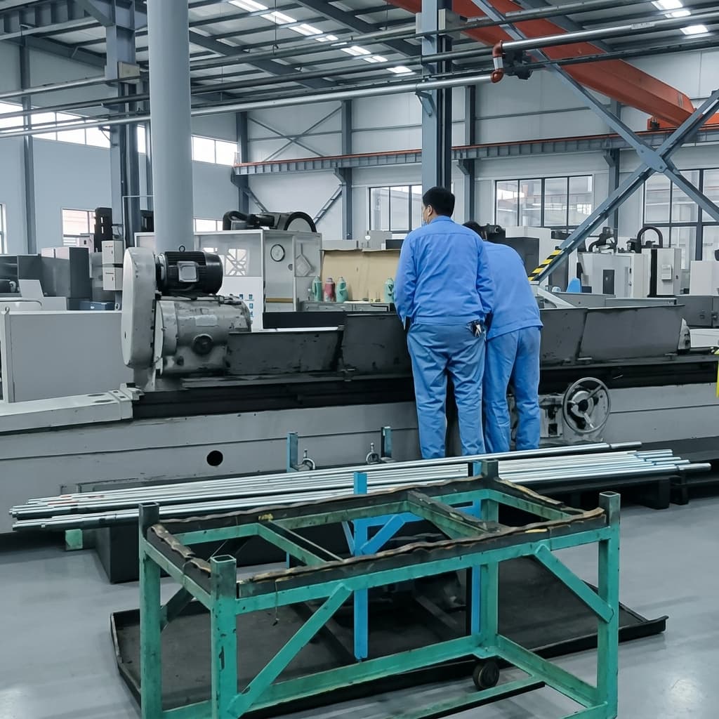
Cover: workshop machinery and metal shafts, shown for manufacturing context. The thermal mechanism is illustrated in the schematic below; neither visual constitutes a thermal-test record.
1. The Thermodynamics of Heat Generation in Miniature Roller Screws
Miniature planetary roller screws convert rotary torque into linear thrust through multiple threaded rollers between the shaft and nut. Efficiency depends on geometry, load, preload, speed, and lubrication. Obtain the supplier's loss estimate or measure running torque at the intended operating point; an unloaded drag measurement does not establish loaded efficiency.
P_loss = T_f * omega = T_f * (2 * pi * n / 60)Where:
- P_loss is the instantaneous thermal dissipation power in Watts (W).
- T_f is the total internal friction torque (N·m), comprising rolling resistance, sliding friction at thread contact flanks, lubricant viscous churning, and planetary timing gear meshing losses.
- omega is rotational velocity (rad/s), where n represents rotational speed in RPM.
For a hypothetical loss torque of 0.02 N·m at 3,000 rpm, this equation gives 6.28 W. It is an assumed operating point, not a rating for a particular micro screw. Average the instantaneous product of loss torque and angular speed over the actual cycle; RMS motor current estimates copper heating and cannot substitute for average mechanical loss power.
Small parts have a larger surface-area-to-volume ratio than geometrically similar large parts. Their practical cooling limitation is often the enclosure and restricted conduction path, rather than surface-area ratio alone. In miniature assemblies, check three heat-flow constraints:
- Restricted Conduction Cross-Section: A 3 mm or 5 mm diameter screw shaft has a cross-sectional area of only 7.1 mm² to 19.6 mm². Thermal conduction along the shaft to end-support bearings is severely throttled by this narrow metallic choke point.
- Minimal Thermal Mass: Estimate initial heating with dT/dt = P_net / (m * c_p). Assuming 20 g of steel, c_p = 460 J/(kg·K), 6.28 W loss, and no heat rejection gives about 0.68 K/s, or 41 K/min. This deliberately adiabatic estimate is not a steady-state prediction: mounting mass and heat rejection substantially change the result.
- Motor Proximity and Thermal Cross-Talk: An integrated motor can add heat through the shaft, nut carrier, or housing. Include motor losses and the actual thermal interfaces in the model. Depending on geometry and cooling, either the shaft or the nut can be hotter; the direction of the gradient must be established for the specific actuator.
A first-order housing estimate is Delta T ≈ P_average * R_thermal. For an assumed 6.28 W and 4 K/W path to ambient, the predicted rise is about 25 K. Estimate the time constant from R_thermal * C_thermal, then validate both warm-up and equilibrium experimentally. A housing temperature alone does not reveal the hottest internal contact.
2. The Mechanics of Preload Runaway (Thermal Clamping)
Preload is applied to eliminate axial backlash and maximize system axial rigidity (K_ax). However, in high-duty micro roller screws, internal preloading establishes the preconditions for a destructive thermal feedback loop.
Thermal Preload Runaway and Viscosity Breakdown Loop in Preloaded Micro Roller Screws
Conceptual schematic, not to scale or a test record. It shows one unfavorable gradient and contact arrangement; another geometry or temperature distribution may reduce preload instead. Film thinning is distinct from lubricant starvation, which concerns insufficient lubricant supply.
The Physics of the Runaway Cycle
- Differential Thermal Growth: A shaft and roller pack can warm faster than a housing-cooled nut. Establish the gradient using a thermal model and instrumented assembly test; this guide does not assert a measured shaft-to-nut temperature difference.
- Contact Geometry Change: Use alpha = 11.5 × 10⁻⁶ K⁻¹ as an approximate steel expansion coefficient for the examples. Confirm the actual material value and temperature interval. Radial growth and axial pitch changes can alter interference, clearance, and load sharing; contact angle and restraint determine the sign of the preload change.
- Preload Change: A local linear screening model is Delta F_p ≈ K_effective * delta_unaccommodated. With assumed K_effective = 100 N/µm and 3 µm displacement, the increase is 300 N. Effective stiffness includes the relevant contact and support load path; it is not a catalog constant for all micro screws. Contact stress does not increase in direct proportion to preload.
- Viscosity Loss: Rising temperature generally reduces base-oil viscosity. A thin film can increase asperity interaction, but temperature alone cannot establish the lubrication regime or a friction coefficient. Distinguish reversible viscosity thinning from irreversible oxidation or grease degradation.
- Stall or Damage: If increasing frictional heat outpaces heat rejection, the assembly may fail to reach an acceptable equilibrium. Rising torque, temperature, and position error together warrant investigation. A current limit or stall is not proof of galling; inspect the mechanism before assigning a failure cause.
3. Nut Preload Architecture vs. Thermal Sensitivity
Choosing the proper internal nut preloading architecture is the primary mechanical defense against thermal preload runaway. Sourcing teams frequently specify "zero-backlash" without indicating whether compliance is permissible, inadvertently forcing the manufacturer to deliver rigid configurations that cannot tolerate thermal transients.
The six-row matrix below separates preload methods, packaging, and compensation concepts. They are not interchangeable product classes. Availability and suitability at miniature diameters require supplier confirmation; no cost or lead-time estimates are implied.
| Configuration or Design Option | Backlash Control Mechanism | Stiffness Trade-Off | Thermal Sensitivity | Qualification Concern | Evidence to Request |
|---|---|---|---|---|---|
| Single Nut with Specified Axial Play | Positive clearance instead of preload | Lost motion on reversal must fit the error budget | Clearance can increase or decrease with gradients | Cold clearance does not ensure hot clearance | Cold/hot backlash and running-torque curves |
| Single Nut with Interference Preload | Selected contact geometry or roller sizing | Contact stiffness depends on the actual preload | Interference can change with differential expansion | Verify hot contact loading and lubrication | Assembly-specific preload and torque envelope |
| Split Nut with Rigid Spacer | Nut halves positioned by a solid spacer | Stiff load path with limited accommodation | Depends on spacer, shaft, nut, and housing growth | Avoid assuming identical steel parts stay isothermal | Coupled growth model and hot-load test |
| Dual Nut with Spring Compliance | Qualified spring pack applies preload | Compliance and possible unloading affect reversal stiffness | Can accommodate displacement within spring travel | Spring bottoming, fatigue, and peak-load separation | Force-travel curve over temperature and load |
| Inverted Roller Screw Packaging | Preload method must be specified separately | Rotor, nut, and supports contribute compliance | Motor heat and cooling determine the gradient | Packaging alone gives no thermal immunity | Motor-on thermal test of the installed assembly |
| Custom Thermal Compensation Element | Designed differential growth or controlled adjustment | Application-specific | Can compensate only within its validated range | Creep, hysteresis, and control failure need assessment | Design analysis, endurance evidence, and availability |
Engineering Takeaway for Sourcing Teams
Specify the required hot and cold behavior before choosing the preload architecture. Duty percentage alone cannot select a nut: speed, load, dwell, external heat, and cooling also matter. Compare a rigid assembly with a compliant alternative against the same stiffness, backlash, and torque limits. Spring compliance can help accommodate growth, but liquid cooling is neither a universal prerequisite for rigid preload nor a guarantee against binding. Send the duty profile for an RFQ review with the required temperature range and unresolved thermal assumptions.
4. Actuator Boundary Mountings and Thermal Expansion Freedom
Even if the nut assembly accommodates internal thermal growth, the overall screw shaft undergoes linear expansion along its axis. How the screw ends are restrained determines whether this expansion manifests as harmless displacement or destructive compressive buckling stress.
The axial elongation of the screw shaft is governed by:
Delta L = alpha * L_tot * Delta T_screwWhere:
- alpha = 11.5 × 10⁻⁶ K⁻¹, the approximate steel value assumed here.
- L_tot is the effective constrained shaft length between bearings in mm.
- Delta T_screw is the average steady-state temperature rise above ambient in °C.
Worked Sizing Example: The Hazard of Fixed-Fixed Micro Mounts
For an illustrative actuator, assume an effective shaft length L = 100 mm, uniform shaft temperature rise ΔT = 45°C, and no growth of the support separation:
Delta L = (11.5 * 10^-6 / K) * 100 mm * 45 K = 0.0518 mm = 51.8 umFor an idealized Fixed-Fixed arrangement with perfectly rigid supports, this free elongation is fully restrained. Real bearings, housings, and joints have compliance and may also expand, so their behavior must be included before treating the result as an assembly load.
The resulting axial thermal compressive force (F_thermal) and internal stress (sigma_thermal) are:
sigma_thermal = E * epsilon = E * (Delta L / L) = E * alpha * Delta T
sigma_thermal = (206,000 MPa) * (11.5 * 10^-6 / K) * 45 K = 106.6 MPa

For a d0 = 4 mm micro shaft (minor core diameter d1 approx 3.2 mm, Area = 8.04 mm²):
F_thermal = sigma_thermal * Area = 106.6 MPa * 8.04 mm² = 857 N
The resulting approximately 857 N is an idealized shaft restraint reaction, not a measured nut preload or a universal failure threshold. Trace where that reaction acts, combine it with service loads, and compare the relevant bearing ratings and shaft buckling limit. A compliant mounting requires a coupled stiffness calculation; a growing housing can substantially change the mismatch. Do not compare the reaction directly with the nut's static rating unless the load path actually carries it through the nut contacts.
The structured table below compares four common bearing mounting architectures:
| Mounting Configuration | Drive End Bearing | Idler End Bearing | Axial Stiffness (K_mount) | Thermal Expansion Accommodation | Critical Buckling Risk Under Heat | Recommended Use Case |
|---|---|---|---|---|---|---|
| Fixed - Free | Axially locating bearing set | Unsupported end | Depends on bearing set and shaft | Free axial growth at the unsupported end | Check deflection and service-load buckling separately | Short unsupported lengths after critical-speed checks |
| Fixed - Floating | Axially locating bearing set | Radial support with designed axial float | Locating end carries thrust | Axial float absorbs growth within its travel | Verify float is not blocked by fits, seals, or assembly error | Assemblies needing radial support and axial accommodation |
| Fixed - Fixed | Axially locating bearing set | Axially locating bearing set | Potentially high; load-path dependent | Growth mismatch creates support reactions | Calculate reactions and stability rather than prohibit the design | Qualified designs with controlled thermal mismatch |
| Fixed - Pre-Tensioned | Locating bearing set | Tensioning arrangement, rigid or compliant | Depends on support and tensioning design | Heating can relax initial tension | Check remaining tension and maximum cold bearing load | Designs with validated pretension over the thermal envelope |
5. Lubricant Viscosity Drop, Film Parameter (Lambda), and Boundary Galling
Lubrication is one contributor to thermal stability. A roller screw can experience rolling and sliding, short-stroke replenishment difficulties, and low entrainment speed during reversals. An elastohydrodynamic lubrication (EHL) film may separate the surfaces at some operating points; it should not be assumed throughout the entire cycle.
Viscosity-Temperature Sensitivity
Request the exact base-oil viscosity-temperature data for the proposed grease. ISO viscosity grade at 40°C alone does not determine viscosity at 70°C or 100°C. Different base oils and viscosity indices give different curves. SKF's lubrication guidance identifies operating viscosity, temperature stability, and additive compatibility as selection inputs; its bearing guidance is background, not a roller-screw film calculation.
For screening: use the lubricant supplier's viscosity-temperature curve
and the actual operating temperature, not viscosity at ambient alone.
Record kinematic viscosity in mm²/s (cSt); dynamic viscosity additionally depends on density. Grease consistency and dropping point are different properties from base-oil viscosity, and dropping point is not the permissible continuous operating temperature. Ask for a grease operating range and relubrication plan that cover the installed mechanism.
The Specific Film Parameter Lambda
For this guide, define a minimum-film screening parameter as the ratio of minimum film thickness to composite RMS surface roughness. State the definition when comparing another model that uses central film thickness instead:
Lambda = h_min / sqrt(Rq_screw^2 + Rq_roller^2)- Lambda around 3 or greater: Often used as a screening indication of substantial surface separation. It does not rule out contamination, starvation, fatigue, or other failures.
- Lambda between about 1 and 3: Indicates increasing likelihood of mixed lubrication and asperity interaction under this convention. Assess additive compatibility and the actual contact model.
- Lambda around 1 or lower: Raises concern about significant asperity interaction. It does not, by itself, predict a seizure temperature, friction coefficient, or wear rate.
Temperature cannot be mapped to these regimes without viscosity, load, speed, roughness, and lubricant-supply inputs. Particularly at reversal, entrainment speed may approach zero even while the actuator is cool. Refer to our PFAS-free lubrication guide for additional selection questions; environmental declarations and regulatory applicability require formulation-specific supplier evidence.
6. Positioning Drift vs. Manufacturing Accuracy Budgeting
Even when thermal expansion is safely absorbed without mechanical binding, thermal elongation introduces linear position drift that can dwarf mechanical machining tolerances.
Ask the supplier to state the accuracy convention, measurement length, reference temperature, and acceptance method. ISO 3408 addresses ball screws; a roller-screw drawing may adopt particular travel-deviation conventions by agreement. A grade label alone does not establish a roller screw's short-stroke tolerance, and a 300 mm travel-deviation limit cannot simply be scaled to a shorter stroke.
The Accuracy Paradox
For a hypothetical error budget, assume a drawing specifies a 3 µm magnitude limit for mechanical travel error over a 60 mm active stroke. This is an example acceptance requirement, not a value inferred from an accuracy class.
If that effective position-measurement length warms uniformly by 25°C relative to its calibration condition:
Delta L_drift = (11.5 * 10^-6 / K) * 60 mm * 25 K = 17.25 umThe calculated 17.25 µm drift is 5.75 times the assumed 3 µm mechanical allowance. A tighter manufacturing tolerance alone would not resolve that thermal contribution. In an actual actuator, determine position relative to the fixed-bearing reference and include housing, push-tube, encoder-reference, and joint growth.
+------------------------------------------------------------------------+
|         LINEAR POSITIONING ERROR BUDGET ACROSS 60 MM STROKE            |
+------------------------------------------------------------------------+
| Assumed Drawing Travel-Error Limit:     [===]  3.0 µm                 |
| Alternative Drawing Limit (Example):    [======] 6.0 µm               |
| Thermal Expansion (ΔT = +10°C):         [=======] 6.9 µm               |
| Thermal Expansion (ΔT = +25°C):         [=================] 17.3 µm    |
| Thermal Expansion (ΔT = +50°C):         [==================================] 34.5 µm
+------------------------------------------------------------------------+
Mitigation Strategies for Precision Positioning
- Direct Linear Scale Feedback: Measure output position relative to the required reference, rather than infer it solely from motor rotation. Direct feedback can correct screw-growth effects visible to the scale, within servo bandwidth. Scale error, its thermal expansion, and unmeasured structure remain in the error budget; it does not compensate every thermal effect.
- Firmware Thermal Model Compensation: If physical packaging prevents adding a linear scale, integrate a calibrated digital thermal model into the servo drive. By sampling a thermocouple placed at the stationary fixed-bearing housing and monitoring cumulative motor current (I²t), the controller estimates Delta T_screw and injects an inverted linear offset:
Offset(t) = -alpha * L_pos(t) * Delta_T_estimated(t) - Material and Reference-Path Design: Use certified expansion data for each relevant material and match the reference path where practical. Changing shaft alloy also changes contact hardness, fatigue capability, corrosion behavior, manufacturing feasibility, and cost. Do not select a material from CTE alone or assume a specialty alloy is available at the required diameter.
For firmware compensation, calibrate temperature estimates against independent displacement measurements across multiple duty cycles. A fixed-bearing thermocouple and motor-current history are indirect inputs; validate warm-up, cool-down, and changing ambient separately. Retain a residual error allowance when gradients depart from the calibration conditions.
7. Actuator Heat Sinking, Thermal Decoupling, and Conduction Design
Preventing thermal clamping requires designing low-thermal-resistance conduction paths out of the roller screw nut and bearing supports into the external machine chassis.
Conduction Bottlenecks in Compact EMAs
- Thread Contacts: Small loaded contact regions and lubricated interfaces impede heat transfer. Their thermal resistance depends on contact geometry, load, roughness, and lubricant; use an assembly model rather than a universal K/W value.
- Miniature Bearing Rings: Bearing balls or rollers create additional thermal resistance points. Heat migrating from the screw shaft into the chassis must bridge the bearing raceways.
Practical Engineering Guidelines for Actuator Design
- Conductive Nut Mounting: Give the nut carrier a defined heat path to the chassis. Assess contact area, contact pressure, and interfaces. Use a thermal interface material only with approval for the locating fit, bolt preload, contamination controls, and lubricant compatibility; paste is not a substitute for a sound mechanical joint.
- Motor Heat Management: Compare cooling the motor at source with reducing conduction into the screw. An insulating coupling can also obstruct a useful heat escape path and alter torsional stiffness, alignment, and fatigue strength. Evaluate the complete thermal and mechanical network before specifying one.
- Housing Heat Rejection: Fins or forced airflow help only when heat reaches the housing and the surrounding air can carry it away. Test the actual enclosure orientation, airflow, mounting surface, and worst ambient. A finned part tested in open air is not representative of a sealed installed pod.
- Special Cooling Architectures: A hollow shaft or internal coolant path is a custom option, not a default micro-screw recommendation. Check remaining core area, buckling, critical speed, seals, manufacturing feasibility, and leakage consequences. Cooling can reduce gradients but cannot guarantee freedom from binding.
8. Sourcing and RFQ Verification Checklist for Thermal Qualification
When procuring miniature planetary roller screws for high-duty or thermally demanding applications, standard catalog specifications are insufficient. Sourcing teams and technical buyers should incorporate the following 8 items into their Request for Quotation (RFQ) package:
- 1. Detailed Duty Profile Definition: Provide stroke, load and velocity versus time, acceleration, dwell, reversals, and operating hours. Request cycle-average screw loss power and separate motor heating estimates, including cold-start and hot-running conditions.
- 2. Thermal Operating Envelope: Specify minimum ambient, maximum ambient, and maximum permissible actuator housing temperature (e.g., -20°C to +85°C).
- 3. Preload Architecture and Compliance: Request the preload method, force-displacement behavior, available accommodation travel, and hot/cold stiffness under both thrust directions. Accept the architecture against the project's requirements rather than a universal duty-percentage rule.
- 4. Preload and Drag-Torque Limits: Agree separate limits for preload, backlash, and running torque. A hot/cold torque ratio may be a project criterion, but torque also includes seals, bearings, load, and lubricant effects; it does not directly measure preload. Record speed, load, and lubrication state for each comparison.
- 5. Lubricant High-Temperature Viscosity Data: Require the supplier to name the exact grease brand and formulation, providing base-oil kinematic viscosity at 40°C, 70°C, and 100°C, along with dropping point and boundary anti-wear qualification records.
- 6. Shaft Boundary End-Fixity Clarification: Document locating and floating supports, available axial float, fit requirements, housing expansion, and expected support reactions. For two axially constrained ends, require a thermal load and stability calculation.
- 7. Material and Temperature Limits: Obtain the screw's material, heat-treatment and dimensional-stability evidence, plus temperature limits for grease, seals, bearings, and adhesives. Use the lowest applicable validated component limit; a bearing stabilization designation does not certify the whole screw assembly.
- 8. Thermal Acceptance Protocol: Agree sample size, installed cooling conditions, worst ambient, load/speed cycle, sampling interval, and abort limits. Run through the relevant mission duration and a predefined temperature/torque stabilization criterion; a fixed 60-minute run does not establish equilibrium for every design. Record position drift and inspect backlash and running torque again after cooling.
Keep the supplier's raw time-series traces, assembly serial numbers, sensor locations, lubricant batch, and test-fixture drawing with the RFQ disposition. Define pass/fail limits before testing, including acceptable temperature slope over an agreed time window and absolute component-temperature limits. Rising torque at stable external load and speed is a diagnostic trigger, not sufficient evidence to identify the failing contact. If the fixture cannot reproduce the installed motor heat or cooling path, record that gap before approving continuous duty.
9. Frequently Asked Questions
Why does an actuator operate smoothly during prototyping but seize in continuous production testing?
A short intermittent test may never reach the temperature gradients of sustained operation. Continuous cycling can expose preload changes, inadequate lubrication replenishment, motor heat input, or constrained shaft growth. It can also expose alignment and bearing problems unrelated to thermal clamping. Compare time-aligned temperature, torque, load, and position traces under the installed cooling conditions before assigning a cause; no universal equilibrium temperature applies.
Can increasing motor servo drive current overcome thermal clamping?
Do not use a higher current limit as the remedy for unexplained hot-running drag. More current can add motor heating and force a damaged or overloaded contact. Stop according to the machine's defined fault procedure, then investigate lubrication, alignment, mounting restraint, and preload. Restore operation only within validated motor and mechanism limits; a torque increase does not automatically require a spring-preloaded redesign.
How much does Belleville-spring preloading reduce axial stiffness compared to a solid spacer?
There is no transferable percentage. Spring rate, orientation of the load path, contact stiffness, and whether one nut half unloads determine the result. For a simple series path, compliances add: 1/K_total = 1/K_nut + 1/K_bearings + 1/K_housing. A real dual-nut arrangement may have changing or parallel load paths, so request measured load-displacement curves over temperature and both thrust directions. Check hysteresis and spring travel as well as nominal stiffness.
What is the maximum allowable temperature for standard 100Cr6 miniature roller screws?
The alloy name alone cannot establish an assembly temperature limit. Heat treatment, dimensional stabilization, hardness requirements, lubricant life, seals, and support bearings all matter. Ask for the supplier-approved continuous and transient limits for the exact assembly and the evidence behind them. Heat-stabilized steel does not prevent elastic thermal expansion and does not extend grease or seal capability automatically.
Is dry solid lubrication (DLC, MoS2) immune to thermal preload runaway?
No. A qualified dry coating avoids liquid base-oil viscosity thinning but does not remove thermal growth, preload variation, or frictional heating. Coating wear, adhesion, environment, and contact loading still require qualification. Select the preload method from the demonstrated thermal and mechanical envelope; dry lubrication neither guarantees immunity nor makes one preload architecture universally mandatory.
10. Engineering Consultation and Sourcing Support
Selecting and sourcing miniature planetary roller screws for thermally demanding actuators requires balancing precision lead accuracy, axial preload stiffness, and thermodynamic heat rejection.
Use Microrollerscrew's published product and engineering pages to prepare a focused inquiry:
- Size and packaging: Compare the 1.5 mm micro roller screw product line and 12 mm miniature series. The 12 mm page is an adjacent sourcing option outside this guide's 1.5–10 mm calculation scope; confirm each configuration's availability and ratings.
- Preload requirements: Supply your hot/cold backlash, stiffness, and drag-torque targets. Ask which architectures can be offered and qualified at your diameter; this article does not promise a specific spring pack or thermal excursion rating.
- Manufacturing evidence: Review the manufacturing overview, then request material and inspection records for the quoted part. Specialty alloys and stabilization treatments require written confirmation.
- Calculation inputs: Consult the engineering resources when preparing loads and duty profiles. Analytical sizing supports selection but does not constitute continuous-duty qualification.
Preparing a high-duty actuator design?
Submit your duty cycle, envelope constraints, ambient temperature envelope, and target accuracy limits to our application engineering team:
Request an Engineering Thermal Consultation and RFQ Review →
11. Sources and Applicability
These sources have different roles. Manufacturer overview pages establish product context and a route to current documentation; they do not substantiate miniature-screw thermal ratings or the example inputs above.
- SKF, “B.4 Lubrication.” Official rolling-bearing lubrication guidance (PDF). Supports selection using operating viscosity, viscosity index, temperature stability, and compatible additives. Bearing guidance does not supply a roller screw's EHL film thickness or failure temperature.
- Rollvis SA. Official planetary and precision roller screw overview. Manufacturer context for roller-screw product families and access to its Downloads section. Request the current catalog and assembly-specific operating instructions; this overview is not a thermal-test report.
- Ewellix / Schaeffler. Official linear-motion product gateway. At this review, the Ewellix address redirects to Schaeffler's linear-motion portal. Use it to locate current supplier documentation, not as evidence of a particular temperature, stiffness, price, or lead time.
Calculation provenance and limits: P_loss = T_loss * omega is a mechanical power balance. Delta L = alpha * L * Delta T assumes a uniform temperature change; with an axial gradient, integrate alpha * Delta T(x) over the effective length. The fully restrained example also assumes linear elasticity, constant modulus, no support motion, and no buckling. None of these calculations proves measured component performance, lubricant life, supplier capability, or suitability for flight or medical service. Reassess the analysis when duty, cooling, material, preload, or mounting changes.
Author

More Posts
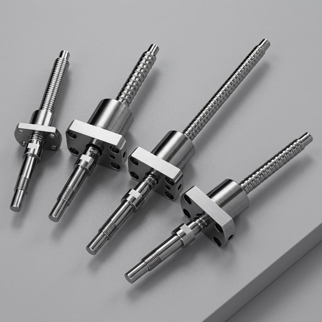
How to Select the Right Inverted Roller Screw for Compact Aerospace Mechanisms
An engineering deep-dive into Inverted Roller Screws (RVi) for flight-control actuators, satellite deployment, and low-backlash aerospace mechanisms.
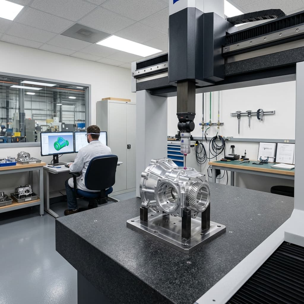
Material Cleanliness and Compliance in Micro Roller Screws: A 2026 Procurement Guide
Procurement guide for micro roller screw material cleanliness, ASTM E45 limits, VIM-VAR steel selection, traceability, and 2026 EU compliance watchpoints.
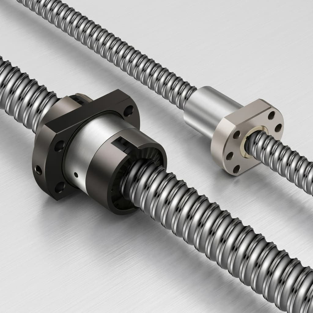
Short-Stroke Dithering and Fretting Wear in Micro Roller Screws: Preventing False Brinelling, Starvation, and Lost Motion in Precision EMAs
Assess short-stroke dithering in micro roller screws: fretting risks, lubricant and preload trade-offs, qualification tests, and RFQ checks. Request review.