
Vacuum and Cryogenic Actuation in Micro Roller Screws: Cold-Welding Prevention, Solid Film Lubrication (MoS2/WS2), and Thermal Shrinkage Budgets
Specify vacuum and cryogenic micro roller screws: compare MoS2/WS2 films, budget thermal shrinkage, and prepare an RFQ with clear qualification requirements.
Vacuum and cryogenic micro roller screws need three linked specifications: a barrier against adhesive wear, a cold clearance budget, and a verified torque and thermal envelope. Selecting a material described as “space grade” or adding a dry film does not establish any of those limits. Buyers should request evidence for the assembled mechanism at its operating temperature, pressure, load, speed, and life requirement.
This guide addresses miniature planetary roller screws with nominal shaft diameters of approximately 1.5–10 mm. Its practical output is an RFQ and qualification plan: what to calculate before ordering, what to ask a coating supplier, and which measurements establish acceptance. It does not assign a vacuum or cryogenic rating to the catalog products linked below.
Published and reviewed November 12, 2026. Scope: Global engineering and procurement evaluation for hard-vacuum mechanisms, with example pressures at or below 10⁻⁶ Torr (approximately 1.33 × 10⁻⁴ Pa) and cooling from approximately 293 K to 77 K. Pressure and temperature are independent specifications. Do not extrapolate this discussion to 20 K or 4 K, liquid-submerged service, reactive propellants, or flight approval without separate evidence.
Evidence boundary: This is a design and sourcing guide, not a report of physical tests. The worked calculations are reproducible screening examples using stated assumptions. The references support general lubrication, outgassing, and thermal-property methods; they do not demonstrate a qualified micro roller screw, a coating lifetime, or a material-specific cryogenic load rating.
Related guides: Pair this analysis with DLC and thin-film surface coatings, thermal expansion and preload control, dynamic load ratings and equivalent duty cycles, and material cleanliness standards. For a project review, submit your mechanism envelope and unresolved qualification requirements.
Cold-Welding and Contact Physics in Vacuum
Cold-welding risk arises when contacting metal surfaces lose their protective films and adhesive junctions develop under load. Rolling contact includes local sliding, so a roller screw can damage a boundary film even when its primary motion is rolling. Vacuum can reduce replenishment of adsorbed surface species, but it does not automatically remove every oxide or guarantee immediate seizure. Surface chemistry, cleanliness, contact stress, sliding history, and the actual lubricant system all matter.
Consequently, neither a pressure threshold nor an assumed Hertzian stress is a universal cold-welding limit. A mechanism that runs freely for a few room-temperature cycles may still fail after storage, a long dwell under preload, or repeated reversals. Ask for breakaway torque after the longest required dwell as well as running torque during motion. Inspect wear and debris after cycling rather than treating low initial friction as proof of endurance.
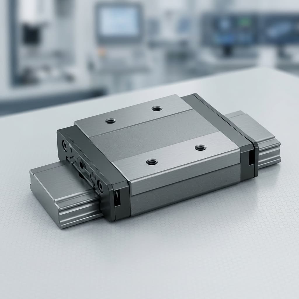 Illustrative positioning hardware only. This image does not show a qualified vacuum or cryogenic roller screw and is not evidence of flight heritage or test performance.
An engineered barrier can reduce direct metal contact. Candidate systems include sputtered MoS2, other qualified lamellar films, and selected soft-metal films. The relevant question is whether the complete substrate, coating, counterface, and environment combination survives the required motion. NASA's Solid Lubrication Fundamentals and Applications examines differences among solid films and between vacuum, humid air, and dry nitrogen. Its environmental comparisons are a reason to request representative testing, not to copy a single friction coefficient into an actuator rating.
For procurement, identify every moving interface. Coating the main thread flanks does not address uncoated timing gears, retainers, support bearings, or end stops. Require a drawing or process map showing treated surfaces, masked areas, final dimensions, and inspection points. The same map should identify inaccessible surfaces where deposition coverage may differ from a flat witness coupon.
Thermal Shrinkage Budgets and Differential CTE Mechanics
Cooling from 293 K to 77 K gives a temperature change of −216 K. Use expansion data over that interval, rather than assuming a room-temperature coefficient remains constant. The NIST cryogenic material-property index provides a starting point for supported grades, including aluminum 6061-T6 and Ti-6Al-4V. Check each dataset's temperature interval, units, reference temperature, and material condition before using it.
For a freely contracting length, the first-order engineering relation is:
ΔL / L0 ≈ integral of α(T) dT, from the assembly temperature to the cold temperature
ΔL ≈ L0 × α_mean × ΔT
Here α_mean is an interval-averaged expansion coefficient, not the value at one endpoint. If a source already provides integrated fractional contraction, use that quantity directly and do not integrate it a second time. Include uncertainty in the material data and the actual component temperatures, particularly during a transient when the shaft, rollers, nut, and housing are not equally cold.
The Structural Differential Clamping Problem
A planetary roller screw contains a shaft, rollers, a nut, timing features, bearings, and mounting interfaces. A titanium or aluminum housing can affect the nut through a press fit, a flange, or a compliant sleeve. These connections transfer contraction differently. A housing coefficient cannot simply replace the nut coefficient in a clearance equation unless the assumed mechanical constraint is justified.
Start by separating three budgets: the housing-to-nut fit, the internal rolling-contact geometry, and the axial preload stack. A press fit may loosen on cooling rather than force the nut to follow the housing. A flange can introduce distortion without uniformly changing the threaded bore. Axial springs can accommodate stack movement while leaving radial interference unresolved. These distinctions determine whether a simple calculation is useful or a coupled structural model is needed.
Analytical Worked Example: a 6 mm Equivalent Bore
The following is an illustrative diametral fit calculation, not a model of the multiple contacts inside a roller screw. Assume an equivalent bore and shaft with a reference diameter D0 = 6.000 mm, initial diametral clearance c0 = 6.00 µm, and a uniform temperature change ΔT = −216 K. For arithmetic clarity, ignore the small difference between the initial bore and shaft diameters in the contraction term.
Assume three interval-averaged coefficients: shaft = 9.6 × 10⁻⁶/K; lower-contraction effective bore = 7.8 × 10⁻⁶/K; higher-contraction effective bore = 19.8 × 10⁻⁶/K. These are assumed inputs, not certified properties for Cronidur, titanium, or aluminum. The effective bore is assumed to follow the selected coefficient fully; actual mounting stiffness and loss of fit can invalidate that assumption.
Change in diametral clearance:
Δc ≈ D0 × ΔT × (α_bore − α_shaft)

Lower-contraction bore:
Δc = 6.000 × (−216) × (7.8 − 9.6) × 10⁻⁶ mm
   = +0.0023328 mm = +2.33 µm
Cold diametral clearance ≈ 6.00 + 2.33 = 8.33 µm

Higher-contraction bore:
Δc = 6.000 × (−216) × (19.8 − 9.6) × 10⁻⁶ mm
   = −0.0132192 mm = −13.22 µm
Cold diametral clearance ≈ 6.00 − 13.22 = −7.22 µm
The second result flags interference in this simplified fit. It does not establish a contact force, a stall torque, or a fracture load. A one-sided radial gap is half the diametral clearance in this concentric bore-and-shaft model. Neither quantity can be converted directly to roller-screw axial backlash without the thread geometry, roller dimensions, contact deformation, and preload arrangement.
The actionable decision is to compare the predicted fit change with tolerances and compliance before ordering hardware. If the tolerance interval crosses interference or loss of retention, revise the mounting concept or analyze it further. Do not resolve the problem by adding the calculated number directly to a finished screw's backlash specification.
Managing the Dual-Temperature Backlash Budget
Define acceptance at both assembly and operating temperatures. For each condition, specify the applied axial measurement load, direction of approach, stabilized component temperatures, permissible backlash or compliance, and maximum breakaway and running torque. “Zero backlash” without a load and measurement method is not an inspectable requirement.
Material matching and compliant preload elements are candidate design measures, not guarantees. Verify a spring's load-deflection behavior, available travel, relaxation, and cryogenic suitability. Include bearings, seals, spacers, coating thickness, and mounting distortion in the tolerance stack. A design that passes at thermal equilibrium must also survive cooldown, warmup, and any heater-induced gradients that occur while motion is commanded.
Heat Rejection and Duty-Cycle Derating in Vacuum
At sufficiently low pressure, ordinary bulk gas convection becomes negligible. Residual-gas heat transfer still depends on pressure, gas species, geometry, and temperature; use a suitable thermal model if it could affect the result. The remaining paths include conduction through contacts, bearings, and mounts, together with radiation to surrounding surfaces.
A useful first screen is to estimate frictional power from measured resisting torque and speed:
P_friction = T_friction × angular speed
angular speed = 2π × rpm / 60
Use frictional torque rather than treating all motor output as loss: some output delivers useful work. Include motor and bearing heating separately when they share the cold structure. A torque increase during cycling can therefore indicate both a lubrication problem and a growing thermal load.
For a lumped steady-state approximation, ΔT ≈ P_friction × R_thermal. If an assumed thermal resistance is 30 K/W and frictional loss is 2 W, the estimated temperature rise is 60 K. That is arithmetic under assumed conditions, not a typical resistance or temperature rise for a 5 mm screw. Contact conductance changes with preload, finish, coatings, and the mounting arrangement.
Radiation depends on emissivity, area, view factors, and the fourth powers of absolute temperatures. It may be small for a polished miniature component near its surroundings' temperature, but cannot be dismissed for every vacuum mechanism. Likewise, a constriction-resistance expression for a circular contact should not be applied directly to a distributed roller line contact without checking its geometry and assumptions.
Select continuous or intermittent operation from the calculated and measured temperature envelope. A pulse-and-rest duty cycle can help, but no fixed motion/dwell ratio applies to all screws. During qualification, record torque and temperatures through representative bursts, long dwells, and reversals. Share the load-speed history and available thermal interfaces when requesting an application review so that motor sizing and heat rejection can be considered together.
Solid Lubricant Architectures: MoS2, WS2, and Soft Metals
PVD Magnetron-Sputtered Molybdenum Disulfide (MoS2)
MoS2 is a layered solid lubricant and a candidate for dry vacuum operation. Performance belongs to a particular deposited film and contact system, not to the chemical formula alone. Humidity exposure, surface preparation, film thickness, and operating conditions can alter behavior. Ask suppliers to distinguish a sputtered film from a bonded formulation and to identify the evidence supporting any proposed doped variant.
Do not assume that a titanium-doped film automatically provides a fixed improvement in wear life. Compare torque and endurance results using a representative counterface and contact condition. A test coupon is useful process evidence, while a coated mechanism test addresses access, coverage, local sliding, and debris retention in the real assembly. The NASA lubrication reference above provides background for these distinctions; it does not qualify the offered coating batch.
Tungsten Disulfide (WS2)
WS2 is another lamellar-film candidate. A WS2 label does not establish a broader usable temperature range or a higher permissible rolling-contact load than MoS2. Require the deposition process, adhesion evidence, counterface condition, and environmental test envelope for the actual formulation. Treat an untested substitution between the two as a change requiring review.
Soft Metallic Films and Vacuum-Compatible Greases
Soft-metal films can be considered where electrical continuity and contact behavior are relevant, but conductivity alone does not prove a suitable lubricant. Lead and gold differ in chemistry, handling constraints, and transfer behavior. Check wear-particle sensitivity, material restrictions, mating surfaces, and contamination requirements before selecting either. No metallic film provides unlimited life or automatic optical compatibility.
A vacuum-compatible PFPE grease is also not a cryogenic rating. Check the exact product and its starting-torque data at the required temperature, rather than imposing one lower-temperature limit on the entire PFPE family. For a 77 K mechanism, require explicit representative evidence before accepting a grease-based design. Heating the lubricant zone is a separate architecture decision with power and thermal-gradient consequences.
Solid Lubricant and Surface Treatment Selection Matrix
This matrix is a procurement screen. It deliberately avoids generic friction coefficients, temperature ratings, and automatic outgassing “Pass” labels: those require formulation-specific reports.
| Candidate system | Reason to evaluate | Principal uncertainty | Evidence needed before selection |
|---|---|---|---|
| Sputtered MoS2 | Dry boundary lubrication in vacuum | Film coverage, storage exposure, wear-through | Deposition specification, witness results, representative torque and life traces |
| Doped sputtered MoS2 | A supplier offers a tailored film formulation | Dopant benefits may not transfer to the required contact | Composition and comparative tests under the proposed environment |
| Deposited WS2 | Alternative lamellar solid film | Process and contact behavior may differ from MoS2 | Adhesion, coverage, and loaded environmental cycling for the actual film |
| Bonded MoS2 | A bonded film fits the geometry and tolerance budget | Binder outgassing, film thickness, debris | Cure history, final dimensions, outgassing report, wear inspection |
| Lead film | Soft-metal contact or conductivity is required | Transfer debris, handling constraints, finite film life | Materials approval and representative torque, continuity, and wear tests |
| Gold film | A specific metallic contact system warrants evaluation | Counterface compatibility and wear behavior | Coating-stack specification and contact-specific endurance evidence |
| PFPE vacuum grease | A qualified product suits a thermally controlled zone | Cold starting torque and contamination | Exact product data plus testing at minimum operating temperature |
| DLC with a lubricant topcoat | A hard underlayer is proposed for wear resistance | DLC formulation and topcoat compatibility | Defined stack, adhesion, and combined-system vacuum testing |
Outgassing Screening Is Separate from Mechanism Qualification
The NASA Goddard Outgassing Database User Guide describes ASTM E595-derived measurements of total mass loss (TML) and collected volatile condensable material (CVCM). It identifies a screening subset with TML no greater than 1.0% and CVCM no greater than 0.10%. These values are material-screening criteria, not an automatic certification of every coating or assembled actuator.
Request results for the actual formulation and preparation condition, including binders, cleaning residues, adhesives, and any process aids. A changed cure or supplier formulation can make an old database entry insufficient. A cold optical surface may require a separate contamination assessment; a material-screening result does not demonstrate acceptable deposition on a colder payload surface or prove that wear particles are harmless.
Metallurgy Selection for Cryogenic Service
Choose material and heat treatment together. Hardness helps define a rolling-contact design, but it does not establish fracture toughness, dimensional stability, or shock tolerance at 77 K. Thread roots, timing features, and retaining grooves need attention because local geometry and defects can dominate failure. Room-temperature bearing fatigue data alone cannot close those questions.
There is no supported universal rule here that bans 100Cr6 below −40°C or assigns a fixed load derating to a precipitation-hardening steel. Likewise, a high-nitrogen steel's reputation is not a substitute for property evidence for the delivered condition. If the supplier lacks applicable data, record the gap and agree on analysis or testing before material release.
Cryogenic Actuator Alloy Comparison Matrix
The following are candidate families for engineering review, not an approved-material list. No grade-specific cryogenic toughness, hardness, or expansion value is assigned without supporting data.
| Candidate material | Possible role to evaluate | Main question | Required sourcing evidence |
|---|---|---|---|
| 100Cr6 / AISI 52100 | Hardened rolling components | Does the delivered condition tolerate cold shock and contact loading? | Heat-treatment records, cleanliness, and applicable cold-property evidence |
| Cronidur 30 | High-nitrogen bearing-steel option | Are material supply and processing qualified for these dimensions? | Material identity, heat treatment, contact-fatigue and cryogenic evidence |
| XD15NW | Another high-nitrogen bearing-steel option | Does the supplier have data for the actual condition and component? | Traceable grade, processing specification, and representative validation |
| AISI 440C | Martensitic stainless rolling components | How do carbide structure and processing affect the design? | Melt and heat-treatment history, microstructure, and application data |
| Precipitation-hardening stainless | Housing, shaft, or structural members | Does strength, hardness, and toughness suit the assigned role? | Exact grade and aging condition with temperature-dependent properties |
| Ti-6Al-4V | Housing or mounting structure | What fit change and thermal path does the interface produce? | Material condition, contraction data, and mounted-fit analysis |
Do not transfer a catalog dynamic load rating to a different material or heat treatment by an assumed percentage. Obtain an agreed rating basis, and keep bearing-style calculated life separate from dry-film wear life. The shorter qualified limit may govern maintenance or mission duration even when the nominal rolling-contact calculation looks favorable.
Mechanical Run-In and Burnishing Protocols
Run-in can establish transfer-film behavior and a torque baseline, but it consumes some of a finite coating life. Its load, speed, stroke, environment, and stopping criteria should come from the coating process and mechanism test plan. There is no universal requirement in this guide for 500–1,000 cycles, a particular humidity, or a percentage of catalog load.
- Preserve the starting condition. Record coating batch, handling exposure, storage, final dimensions, and assembly condition before motion.
- Agree on the environment. Use the supplier-approved dry-gas or vacuum conditions and document temperature and pressure. A dry-gas run is not a substitute for a required cold-vacuum life test.
- Increase duty deliberately. Follow the agreed load and speed sequence while recording breakaway torque, running torque, ripple, and temperature. Define stop limits before testing begins.
- Inspect and reconcile the life budget. Examine accessible surfaces and debris using an approved method. Count run-in, acceptance, integration, and ground-test cycles against the agreed total life allowance.
Do not flush or re-clean a finished coated assembly with an improvised procedure. Cleaning can remove a useful transfer film or introduce contamination. Agree on any debris removal, reinspection, and subsequent torque checks with the supplier. Preserve the traces and inspection records so the delivered assembly has an auditable baseline.
10-Point Thermal-Vacuum and Cryogenic RFQ Sourcing Checklist
Use this checklist to turn a broad request for a “vacuum screw” into inspectable deliverables. Mark unknowns explicitly; unanswered requirements are items for the quotation review, not implied supplier commitments.
- 1. Environmental profile: Specify operating pressure, gas composition where relevant, temperatures, survival limits, cooldown and warmup rates, and whether motion is required during transitions.
- 2. Loads and motion: Supply axial load, side-load constraints, speed, stroke, reversals, dwell durations, lifetime cycles, and any launch, shock, or hard-stop cases.
- 3. Dual-temperature acceptance: Define backlash or compliance and breakaway/running torque limits at stated loads and stabilized temperatures, including measurement uncertainty.
- 4. Housing and thermal interfaces: Identify housing alloy, mounting geometry, fits, tolerances, fastener constraints, heat paths, and the allowable temperature rise.
- 5. Lubrication system: Request the complete coating or grease specification, substrate preparation, treated surfaces, thickness allowance, coverage limitations, and witness records.
- 6. Material and processing evidence: Require traceable material condition, heat treatment, relevant cryogenic properties, and an explicit basis for any quoted load rating.
- 7. Outgassing and contamination: Agree on the applicable ASTM E595 revision and project limits, preparation conditions, reports, particle controls, and any additional optical contamination assessment.
- 8. Run-in and life accounting: Approve the run-in procedure, acceptance traces, inspection criteria, and the cycle allowance for ground testing and mission use.
- 9. Drive margin and verification: Identify the contractually applicable mechanism standard and revision, available motor torque at the operating condition, demand breakdown, uncertainty factors, and test evidence.
- 10. Delivery and change control: Specify packaging atmosphere, storage and exposure limits, installation instructions, traceable records, and which material, coating, or process changes require requalification.
Frequently Asked Questions
Can we test an MoS2-coated micro roller screw on an open-air factory bench?
Only within the exposure and test conditions approved for that coating system. Humidity can change film behavior, but a single humidity cutoff or fixed wear-life penalty cannot be assigned to every MoS2 formulation. Record ambient exposure and ground-test cycles. Use representative cold-vacuum conditions for acceptance requirements that depend on them.
How is axial backlash measured at liquid nitrogen temperature, around 77 K?
Measure displacement under controlled bidirectional axial loading after temperatures stabilize. Depending on the chamber, the setup may use optical displacement sensing or a calibrated external sensor with a mechanical feedthrough. Account for fixture contraction, feedthrough compliance, sensor thermal drift, and measurement uncertainty. Distinguish backlash from elastic deflection instead of interpreting all reversal motion as lost clearance.
Does vacuum make an uncoated roller screw cold-weld instantly?
No universal time-to-seizure follows from pressure alone. Loss of protective surface films and adhesive wear can raise risk, while contact load, sliding, materials, and prior handling affect the outcome. Require testing that includes relevant starts, reversals, dwell periods, and post-test inspection. A short successful demonstration does not establish service life.
What mechanism torque margin is required by space standards?
Use the standard revision and tailoring invoked by the project. If ECSS-E-ST-33-01 is specified, obtain the applicable clauses and agreed margin method rather than using an unexplained multiplier from an article. Separate useful output load, friction, acceleration, and other resisting torques, and evaluate motor capability at the actual temperature, supply, and speed.
For arithmetic only, a capacity-to-demand ratio of 2 corresponds to a fractional reserve of 1 under the definition below. This is not asserted to be the definition or acceptance threshold of any specific standard:
Capacity ratio = available torque / assessed demand
Fractional reserve = capacity ratio − 1
State the definition beside every reported margin. Otherwise, “margin 2” can mean either twice the demand or a 200% reserve, which are different requirements.
When should we select a metallic film instead of MoS2 or WS2?
When contact-specific evidence supports the metallic system for the application's electrical, environmental, wear, and contamination needs. Electrical conductivity is one selection input, not sufficient proof. Ask for the coated counterface configuration and particle behavior, and verify any restrictions on lead or other proposed materials through the project's materials approval process.
How does vacuum bakeout affect preloaded roller screws?
Bakeout can change fits, preload, lubricant condition, and contamination behavior. Heating an aluminum housing relative to steel components may loosen one interface while another constraint increases load. Model the actual assembly and use a supplier-approved temperature and duration. After the agreed cycle, recheck dimensions, torque, and cleanliness at the required acceptance conditions.
Sources and References
These three primary sources were checked for this review on November 12, 2026. They establish background methods and evidence requirements; none is presented as a test certificate for the products linked here.
- NASA Glenn Research Center — Kazuhisa Miyoshi (2000): Solid Lubrication Fundamentals and Applications, NASA/TM-2000-107249/CH6, NTRS document 20010017158. Background on selected solid films, environmental effects, and variables affecting friction and wear.
- NASA Goddard Space Flight Center: Outgassing Database User Guide. Describes ASTM E595-derived testing, TML/CVCM screening, preparation history, and limitations when using database results for material selection. The link redirects to NASA Goddard's current guide.
- National Institute of Standards and Technology: Cryogenic Material Properties — Index of Material Properties. Starting point for temperature-dependent properties of supported grades. The assumed coefficients in the worked example are not claimed to be extracted measurements from this index.
Next Steps for Actuator Development
For sizing and geometric packaging context, compare the baseline envelopes of the 1.5 mm micro roller screw, 2 mm micro roller screw, and 10 mm micro roller screw. For a larger packaging study, review the 12 mm planetary roller screw. These catalog links do not imply vacuum, cryogenic, propellant, or flight qualification.
Prepare the operating profile, housing interfaces, required life, and acceptance limits before requesting a custom variant. Contact our engineering team with your RFQ parameters to discuss feasibility, missing property data, and a proposed verification plan. Agree on the evidence and acceptance criteria before treating a quoted configuration as qualified for the mission.
Author

More Posts
DLC and Thin-Film Surface Coatings in Micro Roller Screws: Mitigating Hertzian Micro-Slip, Preventing Eggshell Delamination, and Sizing Tolerances for Extreme-Duty EMAs
Specify DLC coatings for micro roller screws: check substrate support, thickness, tolerances, and adhesion tests. Use the RFQ checklist for engineering review.

Navigating PFAS-Free Lubrication for Micro Roller Screws: 2026 Compliance Guide
A comprehensive guide for procurement and engineering teams on transitioning to PFAS-free lubrication for miniature planetary roller screws in high-load, high-temperature applications.
The Hidden Costs of Micro Roller Screw Integration: Specifying Custom End Machining
Specify custom end machining for micro planetary roller screws: RFQ tolerances, runout risks, heat-treatment limits, and when to request factory support.