
DLC and Thin-Film Surface Coatings in Micro Roller Screws: Mitigating Hertzian Micro-Slip, Preventing Eggshell Delamination, and Sizing Tolerances for Extreme-Duty EMAs
Specify DLC coatings for micro roller screws: check substrate support, thickness, tolerances, and adhesion tests. Use the RFQ checklist for engineering review.
DLC coatings for micro roller screws can reduce adhesive wear in boundary-lubricated rolling-sliding contacts, but they do not replace substrate strength, lubrication design, or assembly qualification. For an extreme-duty electromechanical actuator (EMA), select the coating only after checking three questions: can the hardened steel support the contact load, can the deposition process preserve that steel's properties, and can the finished thread geometry accommodate the complete coating stack?
A coating specified as only a few micrometers thick can still consume a meaningful part of a miniature screw's fit allowance. Coating thickness is measured normal to the flank; its effect on pitch diameter depends on flank angle. Applying a simple twice-thickness allowance to every thread form can produce an incorrect grinding offset. This guide separates an illustrative geometric calculation from the production measurements needed to approve the assembly.
Published and reviewed November 9, 2026. Scope: Global engineering and procurement screening for miniature planetary roller screws with nominal shaft diameters of 1.5–10 mm. The focus is boundary lubrication, short-stroke motion, and demanding EMA environments. Vacuum, medical, aerospace, and corrosive applications require additional application-specific qualification.
Evidence boundary: This article combines the cited coating literature and test-method descriptions with an analytical worked example. It reports no proprietary coating trials, measured roller-screw life improvement, or certified supplier capability. Example loads, dimensions, and tolerances are chosen inputs, not catalog ratings or universal acceptance limits.
Related guides: Pair this analysis with dynamic load ratings and equivalent duty cycles, preload methods and backlash elimination, short-stroke fretting mitigation, and thermal expansion and preload control. For a specific design, submit the drawing and operating envelope for engineering review.
The Tribological Dilemma in Micro Roller Screws
Roller screws combine rolling with local sliding at the interacting thread flanks. The balance depends on geometry, load sharing, speed, and contact location. Lubrication may move between elastohydrodynamic, mixed, and boundary regimes during one operating cycle. Starts, reversals, and small oscillations deserve separate attention from steady rotation because entrainment and lubricant replenishment change.
Miniature assemblies also offer little free volume for grease. A small reservoir does not prove starvation, but it makes grease quantity, migration, relubrication access, and sealing useful design questions. A coating may reduce surface damage when lubricant films become thin; it cannot establish that lubricant will reach every loaded contact.
Diamond-like carbon is a family rather than one material. Hydrogen content, dopants, interlayers, surface finish, counterface, and environment all influence friction and wear. Fraunhofer IST lists different carbon coating systems and test-specific properties in its Friction Reduction and Wear Protection brochure. Such data are useful for screening candidates, but a laboratory coefficient is not an actuator efficiency or service-life guarantee.
Ask the supplier to compare a coated candidate with an otherwise equivalent uncoated, lubricated baseline. Record breakaway torque, running torque, backlash, temperature, surface condition, and debris at defined intervals. If the baseline already meets the mission without wear or torque instability, adding a coating may introduce avoidable cost and dimensional risk.
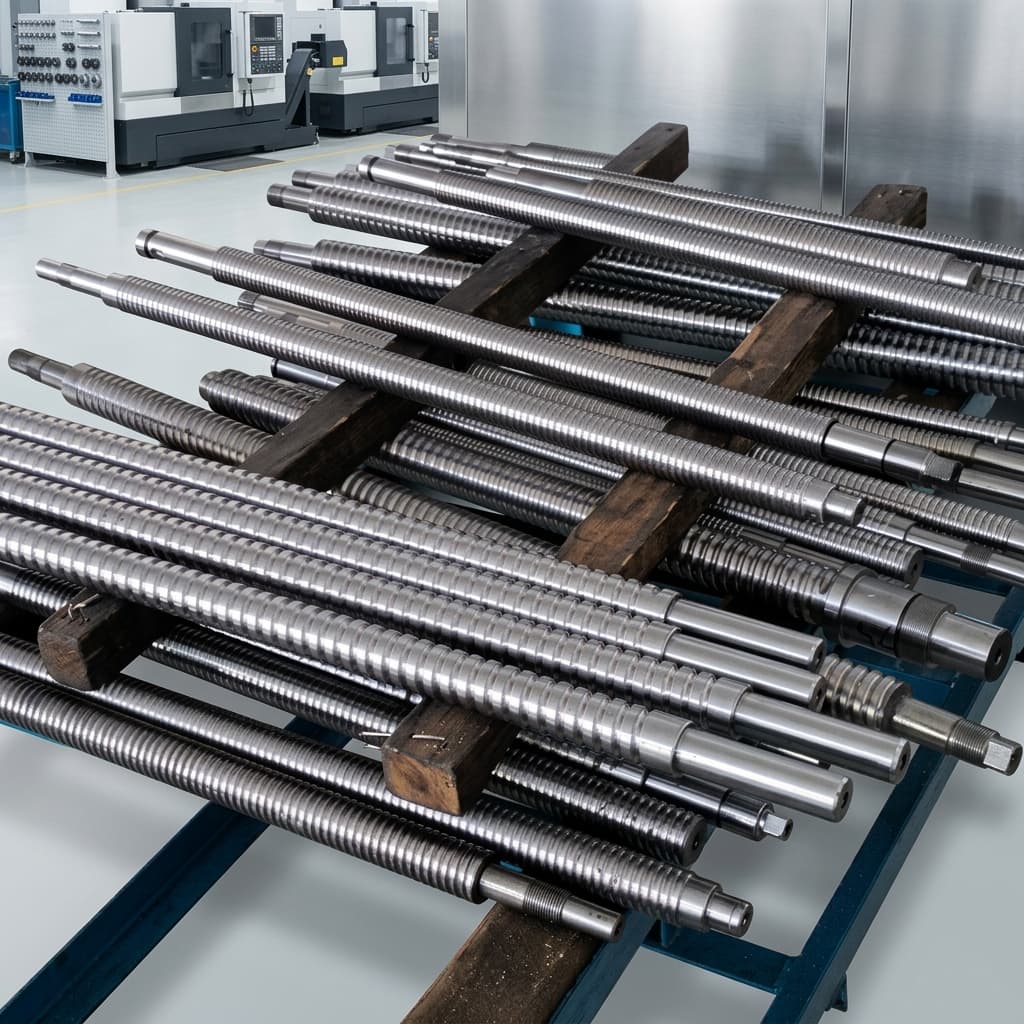
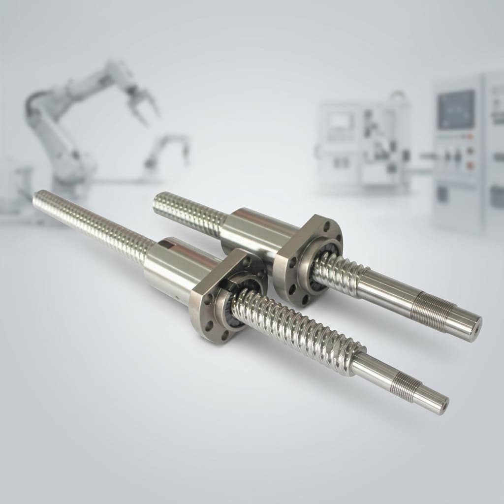
Illustrative screw-manufacturing image. It does not establish miniature dimensions, DLC coverage, surface roughness, or coating performance.
Subsurface Stress Mechanics and the Eggshell Effect
A thin hard film depends on support from the steel beneath it. If the substrate deforms plastically, the film can bend, crack, and detach. This support-related failure is often described as the eggshell effect. It is one possible delamination mechanism; poor cleaning, residual coating stress, inadequate interlayers, and fatigue can also cause separation. A failed adhesion coupon alone cannot identify which mechanism operated in a screw.
Depth of Maximum Shear Stress
For an ideal smooth, frictionless Hertzian line contact, the maximum principal shear stress is approximately 0.30 × p0 at a depth of approximately 0.78 × b, where p0 is peak contact pressure and b is contact half-width. These are an elastic half-space approximation, not a model of every helical roller-screw contact. Finite contact length, local curvature, friction, edge loading, and unequal roller loading change the stress field.
As a chosen analytical example, take p0 = 2.5 GPa and b = 25 µm. The estimates are maximum shear ≈ 0.75 GPa and depth ≈ 19.5 µm. A 2 µm coating would be much thinner than that depth. The practical inference is that film hardness alone cannot establish load capacity. These two contact inputs must come from the actual geometry and load analysis before using the example for a drawing decision.
Do not infer a minimum hardness or case depth from shaft diameter alone. Request the substrate's heat-treatment condition, hardness profile where applicable, effective hardened depth, and post-process dimensional stability. Agree how the supporting material will be assessed after deposition. A hardness conversion or a generic bearing-steel designation does not prove that the actual thread flank remains supported under repeated loading.
Preventing Support-Related Delamination
Follow a failure chain rather than specifying one universal hardness number. Establish contact loading and substrate condition first, confirm the deposition cycle preserves that condition, then verify adhesion and assembled performance. Retain failed parts and inspect both the exposed steel and detached film. Debris generated by a coating can circulate through other contacts, so cleanliness and particle inspection belong in the qualification plan.
A surface-hardened steel also needs an adequate supporting hardness profile below the coating. There is no case-depth multiplier in this guide that approves every thread geometry. Compare the calculated stress distribution with material properties and the actual hardened layer, including grinding allowance and any thermal exposure after hardening.
Deposition Temperature vs. Substrate Tempering Limits
The maximum acceptable part temperature depends on the alloy, its actual heat treatment, previous stabilization, process duration, and required dimensional stability. A coating name does not define one deposition temperature. DLC may be produced by physical vapor deposition (PVD), plasma-assisted chemical vapor deposition (PACVD), or hybrid processes, with different thermal and ion-bombardment histories.
Do not treat a chamber setpoint as the measured component temperature. Include cleaning, ion etching, deposition, and any post-treatment in the approved thermal cycle. Ask how temperature is measured on representative fixtured parts and how the manufacturer verifies hardness and geometry afterward. Exceeding a previous tempering condition can alter properties, but it is inaccurate to describe every such exposure as complete annealing.
Substrate and Coating Thermal Compatibility Matrix
This is a documentation matrix, not a list of approved temperatures. The supplier and heat-treatment specialist must establish numerical limits for the purchased condition.
| Substrate family | Heat-treatment information to request | Coating-process question | Evidence before release |
|---|---|---|---|
| 100Cr6 / AISI 52100 | Actual hardening, tempering, and hardness records | Can the full cycle preserve hardness and dimensions? | Representative post-process hardness and geometry checks |
| Stabilized bearing steel | Meaning of the supplier's stabilization designation | Does the approved condition cover deposition time and part temperature? | Traceable thermal history and dimensional measurements |
| AISI 440C | Tempering condition and any sub-zero treatment | Are cleaning and deposition compatible with the selected condition? | Hardness, corrosion, and size verification as required |
| High-nitrogen bearing steel | Exact alloy specification and delivered condition | Is the proposed interlayer compatible with this heat treatment? | Material-specific process qualification |
| Precipitation-hardening stainless | Aging condition and supporting mechanical properties | Is substrate support sufficient before coating is considered? | Contact assessment and post-process property checks |
| Case-hardened steel | Hardness-depth profile and remaining case after grinding | Will the process preserve the supporting layer? | Agreed profile checks and finished-flank inspection |
The purchasing implication is straightforward: quote the coating and heat-treatment route together. A cheaper coating process is not interchangeable if its thermal cycle invalidates the substrate condition or requires a different final grinding sequence.
Thin-Film Coating Architectures Compared
Use the following candidates to structure a supplier discussion. No row establishes a preferred film for all miniature screws; the finished coating/substrate/counterface/lubricant combination is the unit being qualified.
| Candidate | Potential reason to evaluate it | Main uncertainty | Useful qualification comparison |
|---|---|---|---|
| Uncoated, finished bearing steel | Baseline with established lubrication and fit | Boundary wear during reversals or starvation | Same duty cycle and lubricant as the coated candidate |
| WC/C or tungsten-containing carbon | Candidate for rolling-sliding wear control | Exact composition, interlayer, and additive interaction | Coated roller against the intended finished steel counterface |
| Hydrogenated DLC, a-C:H | Candidate for adhesive-wear and friction reduction | Hydrogen content, environment, and transfer-layer stability | Air or vacuum testing at the actual load and motion conditions |
| Hydrogen-free ta-C | Candidate where hardness and wear resistance are priorities | Residual stress, finish, and counterface response | Adhesion, roughness, debris, and endurance measurements |
| CrN or another hard nitride | Candidate for a specific wear or chemical exposure | Deposition compatibility and achievable friction | Actual fluid exposure plus lubricated torque and wear tests |
| MoS2-based solid lubricant | Candidate for selected dry or vacuum mechanisms | Storage atmosphere, humidity, and limited lubricant inventory | Storage conditioning followed by representative vacuum cycling |
Environmental dependence is particularly important. The experimental 2019 H-DLC transfer-layer study reports that load and atmosphere affect transfer-layer stability. It supports testing the intended environment, not assuming that all DLC films work dry in vacuum.
Asymmetric Coating Strategy: Qualify the Contact Pair
Coating only the satellite rollers is a useful candidate architecture: it limits coated component count and allows comparison against polished steel shaft and nut flanks. It is not a universal rule. A coated/coated pair can also be appropriate when the specific film, finish, and environment have been qualified. There is no general prohibition on DLC-on-DLC contact.
Map both roller-to-shaft and roller-to-nut contacts. A successful shaft-side coupon result does not automatically qualify the nut-side contact. Internal nut threads may present different deposition access and thickness-uniformity challenges from exposed rollers. Ask for coverage evidence at the root, crest, and loaded flank locations rather than relying on a flat witness coupon alone.
Also define masking, fixture contact locations, edge preparation, and post-coat finishing. A polished coupon with good adhesion does not establish that an inaccessible internal flank has the same coating stack or surface condition.
Procurement and Engineering Decision Matrix by Duty Profile
These six scenarios identify the evidence to request, rather than prescribing an unverified optimum coating or regulatory approval.
| Duty profile | Question driving coating selection | Test conditions to specify | Release evidence |
|---|---|---|---|
| High-frequency dithering joints | Does the film reduce damage during limited lubricant replenishment? | Actual reversal amplitude, load, frequency, and grease | Torque trend, wear inspection, and backlash change |
| Aerospace EMAs | Can the complete pair survive the specified mission envelope? | Relevant temperature, shock, load, and holding cases | Program-specific endurance and failure assessment |
| Semiconductor vacuum stages | Are friction, particles, and outgassing acceptable together? | Vacuum level, bakeout, cleanliness, and stroke history | Vacuum endurance plus contamination measurements |
| Surgical robotic mechanisms | Does processing remain compatible with cleaning and intended contact? | Relevant cleaning or sterilization exposure and particle limits | Device-specific material and particulate evaluation |
| Downhole metering | Can the stack withstand the actual fluid and temperature exposure? | Fluid chemistry, pressure, thermal cycle, and mechanical load | Combined exposure and motion testing |
| Space deployment mechanisms | Will storage and launch history affect dry operation? | Humidity exposure, storage duration, vacuum, and cold starts | Conditioned deployment tests and debris inspection |
For medical procurement, a coating material description is not device-level biocompatibility approval. Similarly, a salt-spray duration alone cannot qualify downhole chemistry. Keep the application owner responsible for defining the test environment and acceptance criteria.
Dimensional Tolerance Stack-Up and Pre-Machining Compensation
Travel accuracy, axial backlash, preload, and coating thickness are separate requirements. An accuracy class does not define running clearance. Put the actual finished fit, measuring load, temperature, and torque requirements on the drawing instead of deriving a clearance from a travel-accuracy label.
Mathematical Relationship: Normal Thickness vs. Pitch Diameter
Consider an ideal symmetric V profile in an axial-radial section, with included angle 2α; each flank makes angle α with the radial centerline. Assume straight flanks and a uniform normal coating thickness t. A radial translation Δr produces normal displacement Δr × sin α, giving:
- Equivalent external pitch-diameter increase:
Δd = 2t / sin α. - Equivalent internal pitch-diameter decrease: the same magnitude, with the opposite sign.
- For an assumed 90° included profile,
α = 45°, soΔd ≈ 2.828t.
This is a two-dimensional profile estimate. Helix angle, crowned roller profiles, actual contact normals, coating distribution, and the manufacturer's gauging definition require a geometry-specific correction. Use the model to expose allowance errors; do not transfer it directly to every roller-screw grinding drawing.
Worked Example: A Roller Coated to 2.0 ± 0.3 µm
Assume a 90° included V profile, the shaft and nut remain uncoated, and total deposited thickness, including interlayers, is 2.0 ± 0.3 µm. The equivalent roller pitch-diameter increase is:
- Minimum:
2 × 1.7 / sin 45° ≈ 4.81 µm. - Nominal:
2 × 2.0 / sin 45° ≈ 5.66 µm. - Maximum:
2 × 2.3 / sin 45° ≈ 6.51 µm.
Under this idealization, the nominal external pre-coat pitch diameter would be about 5.66 µm below the desired final value. The coating alone contributes approximately ±0.85 µm of equivalent diameter variation. If a hypothetical finished pitch-diameter tolerance were ±1.50 µm, a simple worst-case allocation would leave only ±0.65 µm for all other contributors. That remainder must accommodate machining, geometry, measurement, and any other allocated variation; it is not an assertion that a supplier can manufacture the part to that budget.
At one interface, coating the roller alone reduces the local normal gap by t. Coating both contacting flanks reduces it by t1 + t2. Neither result by itself predicts total axial backlash: the assembly also depends on both contact interfaces, roller positioning, thread geometry, and elastic preload. Do not add equivalent diameters and call the sum an axial-clearance change.
Design Rules for Engineering Drawings
- State that functional dimensions and inspection acceptance apply after coating and any final finishing.
- Keep supplier-approved pre-coat dimensions on the controlled process drawing, referenced to the actual profile and gauging method.
- Specify total stack thickness separately from functional topcoat thickness, with measurement locations and uncertainty.
- Include allowance for coating variation, grinding variation, roughness, thermal effects, and measurement error.
- Verify finished backlash or preload and breakaway/running torque under the agreed load and temperature.
Before releasing machining offsets, request a drawing and tolerance-budget review with the screw maker and coating specialist. Provide the profile definition and final assembly requirement so the review can address the complete fit.
Adhesion Qualification: VDI 3198 and ASTM C1624
Adhesion testing is a process-control tool, not a direct service-life rating. A witness coupon should represent the purchased steel condition, surface preparation, coating batch, and relevant fixture exposure. It cannot reproduce every curvature or deposition-shadowing effect on a miniature thread.
Rockwell Indentation and VDI 3198 References
VDI 3198 and HF classifications appear in legacy coating specifications. Indentation is destructive at the test location, including on a witness coupon. If a supplier proposes this approach, confirm the contractual method and edition, suitability for the coating/substrate system, imaging requirements, and agreed visual acceptance criteria with the laboratory. Do not assume a cited legacy method is the current requirement for the program.
An HF1/HF2 acceptance requirement may be agreed for a particular supply contract, but it is not a universal roller-screw approval rule. Do not transfer destructive coupon indentation directly onto a precision functional flank unless the inspection plan explicitly permits it. Retain identifiable images and evaluate changes against the qualified process baseline.
Quantitative Scratch Testing: ASTM C1624
ASTM C1624-22 describes practical adhesion and damage testing of hard ceramic coatings, including DLC, on substrates. Its public scope explains that measured response depends on the coating/substrate system and test setup. It does not measure fundamental interface bond strength or prescribe universal roller-screw acceptance loads.
Define damage events microscopically and record stylus geometry, loading conditions, scratch speed, specimen preparation, and images. Acoustic or friction signals can supplement inspection. Labels such as Lc1, Lc2, and Lc3 need agreed event definitions; fixed thresholds of 25, 45, or 65 N cannot be copied between different films and laboratories as a general qualification rule.
Develop acceptance limits using specimens from the qualified process and correlate them with relevant component tests. A good scratch result still leaves dimensional fit, contact fatigue, torque stability, and contamination to be verified on assembled hardware.
8-Point Engineering and Procurement RFQ Checklist
Use these clauses to make supplier quotes comparable. Resolve incomplete inputs before ordering qualification hardware; record exceptions explicitly rather than accepting an undefined “DLC equivalent.”
- 1. Substrate and heat treatment: Identify alloy, delivered condition, traceability, supporting hardness or depth requirements, and how properties will be checked after processing.
- 2. Approved thermal cycle: Specify the agreed maximum representative part temperature, duration, measurement method, and records for cleaning, etching, deposition, and post-treatment.
- 3. Coated components and contact pairs: List roller, shaft, and nut scope, masking, fixture locations, counterface finish, and the lubricant or dry environment being qualified.
- 4. Complete coating stack: Identify interlayers and topcoat, total and functional thickness ranges, inspection locations, measurement method, and uncertainty. Include coverage of difficult thread regions.
- 5. Finished surface quality: Agree roughness parameters, evaluation direction, sampling method, defects, edge condition, and any post-coat finishing. Set limits from the qualified combination.
- 6. Adhesion evidence: Name the test method and edition, representative coupon condition, damage definitions, agreed acceptance limits, batch images, and disposition of nonconforming results.
- 7. Finished dimensions and torque: Distinguish pre-coat process dimensions from final acceptance. Define backlash or preload, runout, breakaway/running torque, load, temperature, and measurement uncertainty.
- 8. Lot release and change control: Require batch traceability, inspection results, qualification references, packaging/storage conditions, and notification before changing composition, fixtures, process, or subcontractor.
Procurement should also separate development costs from recurring production price. Ask which quotation lines cover masking and fixtures, witness coupons, destructive measurements, prototype endurance, minimum batch charges, and rejected-part disposition. A low unit coating price without those items can be misleading when comparing complete finished assemblies.
Frequently Asked Questions
Can we buy stock micro roller screws and send them out for PVD coating?
Only after the original manufacturer confirms the route. Existing fit allowance, heat treatment, disassembly/reassembly requirements, and finished inspection must be reviewed. Some assemblies may accommodate a qualified modification, while others require new pre-coat machining dimensions. A stock part is not automatically suitable, and coating does not automatically make it unusable.
What is the difference between WC/C and hydrogenated DLC?
WC/C describes a tungsten-carbide/carbon coating system; a-C:H denotes hydrogenated amorphous carbon. Supplier formulations, gradients, interlayers, and processes vary. Compare the specified stack and its measured performance against the intended counterface and lubricant. The family name alone cannot rank ductility, friction, additive compatibility, or rolling-contact life for a particular screw.
Why not use TiN or another hard nitride?
A hard nitride may be a candidate for a defined wear mechanism, but it is not automatically a low-friction substitute for a carbon film. Confirm deposition compatibility with the actual substrate heat treatment and test the lubricated pair. Avoid rejecting or approving a process using a generic temperature assigned to its coating name.
How can coating affect back-driving and holding torque?
Changing friction can change breakaway and back-driving behavior. Measure the coated assembly over its load and temperature range and after relevant wear exposure. A sliding-thread self-locking formula cannot alone predict a planetary roller screw's holding behavior. If the actuator must hold position without power, qualify the complete holding and braking arrangement against the application requirement.
Can a coated micro roller screw run completely dry?
Possibly, for a qualified film, contact pair, and mission. Dry air, vacuum, and cryogenic service are different test environments. There is no supported universal percentage by which to reduce a lubricated catalog life rating for a coated dry-running assembly. Ask for representative endurance data, allowable torque drift and debris limits, and a stated failure criterion before making a life commitment.
How should a laboratory measure thickness on miniature threads?
Agree a method that suits the geometry and film chemistry. Ball cratering or cross-sectional microscopy can provide local thickness information, but destructive sampling and access need planning. A witness coupon measures the coupon, so establish how it relates to thread coverage. X-ray fluorescence is not a universal direct thickness method for carbon-rich DLC; ask what element or calibrated layer model it actually measures. Report measurement uncertainty instead of assuming a fixed accuracy for every method.
Sources and References
The following sources support coating-family selection, environmental dependence, and test-method scope. None validates a specific micro roller screw's load rating, life, grinding offset, or suitability for a regulated application.
- Fraunhofer Institute for Surface Engineering and Thin Films IST: Friction Reduction and Wear Protection, technical brochure, especially the coating-systems table. Provides coating-family and test-context information; its laboratory properties are not assembly ratings.
- Materials (2019), 12(9), 1550: Key Role of Transfer Layer in Load Dependence of Friction on Hydrogenated Diamond-Like Carbon Films in Humid Air and Vacuum. Experimental evidence of load- and environment-dependent transfer-layer behavior for the studied H-DLC system; not a roller-screw endurance test.
- ASTM International, ASTM C1624-22: Standard Test Method for Adhesion Strength and Mechanical Failure Modes of Ceramic Coatings by Quantitative Single Point Scratch Testing. Public scope and significance explain method dependence and practical adhesion assessment. Obtain the specified edition for the actual laboratory procedure.
Next Steps for Actuator Development
Start with the operating envelope and the finished assembly requirement. For dimensional context, compare the 1.5 mm micro roller screw and 10 mm micro roller screw product series. The 12 mm planetary roller screw is an adjacent size comparison, outside this guide's 1.5–10 mm focus. Product listings do not establish availability of the coating combinations discussed here.
For a coating feasibility review, provide shaft diameter and lead, thread profile if available, load/time history, speed and reversal amplitude, temperature, lubricant or vacuum conditions, target backlash or preload, required life, quantity, and drawing status. Contact our engineering team with this RFQ package to discuss candidate processes, the dimensional budget, and the evidence needed before production release.
Author

More Posts
Material Cleanliness and Compliance in Micro Roller Screws: A 2026 Procurement Guide
Procurement guide for micro roller screw material cleanliness, ASTM E45 limits, VIM-VAR steel selection, traceability, and 2026 EU compliance watchpoints.
How to Select the Right Inverted Roller Screw for Compact Aerospace Mechanisms
An engineering deep-dive into Inverted Roller Screws (RVi) for flight-control actuators, satellite deployment, and low-backlash aerospace mechanisms.
Miniature Linear Actuators in Humanoid Robotics: The Role of Micro Roller Screws
Where micro planetary roller screws can fit when humanoid robotics teams need compact, high-load linear actuation.